Dodge Dakota (ND). Manual — part 744
P0522-OIL PRESSURE TOO LOW (CONTINUED)
4.
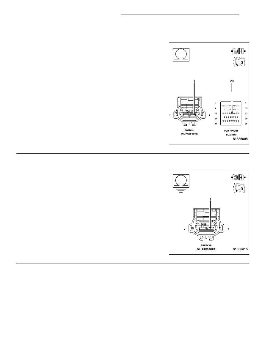
(G6) OIL PRESSURE SWITCH SIGNAL CIRCUIT OPEN
CAUTION: Do not probe the PCM harness connectors. Probing
the PCM harness connectors will damage the PCM terminals
resulting in poor terminal to pin connection. Install Miller Special
Tool #8815 to perform diagnosis.
Measure the resistance of the (G6) Oil Pressure Signal circuit from the
Oil Pressure Switch harness connector to the appropriate terminal of
special tool #8815.
Is the resistance below 5.0 ohms?
Yes
>> Go To 5
No
>> Repair the open in the (G6) Oil Pressure Signal circuit.
Perform POWERTRAIN VERIFICATION TEST. (Refer to 9
- ENGINE - STANDARD PROCEDURE)
5.
(G6) SIGNAL CIRCUIT SHORTED TO GROUND
Measure the resistance between a known good ground and the (G6)
Oil Pressure Signal circuit in the Switch connector.
Is the resistance below 100 ohms?
Yes
>> Repair the short to ground in the (G6) Oil Pressure Signal
circuit.
Perform POWERTRAIN VERIFICATION TEST. (Refer to 9
- ENGINE - STANDARD PROCEDURE)
No
>> Go To 6
9 - 514
ENGINE ELECTRICAL DIAGNOSTICS
ND
P0522-OIL PRESSURE TOO LOW (CONTINUED)
6.
PCM
NOTE: Before continuing, check the PCM harness connector terminals for corrosion, damage, or terminal
push out. Repair as necessary.
Using the schematics as a guide, inspect the wire harness and connectors. Pay particular attention to all Power and
Ground circuits.
Were there any problems found?
Yes
>> Repair as necessary.
Perform POWERTRAIN VERIFICATION TEST. (Refer to 9 - ENGINE - STANDARD PROCEDURE)
No
>> Replace and program the Powertrain Control Module per Service Information.
Perform POWERTRAIN VERIFICATION TEST. (Refer to 9 - ENGINE - STANDARD PROCEDURE)
ND
ENGINE ELECTRICAL DIAGNOSTICS
9 - 515

P0532-A/C PRESSURE SENSOR CIRCUIT LOW
9 - 516
ENGINE ELECTRICAL DIAGNOSTICS
ND

P0532-A/C PRESSURE SENSOR CIRCUIT LOW (CONTINUED)
For the Engine circuit diagram (Refer to 9 - ENGINE - SCHEMATICS AND DIAGRAMS).
For a complete wiring diagram Refer to Section 8W.
•
When Monitored:
Engine running, AC is learned, and AC Clutch Relay energized.
•
Set Condition:
The A/C pressure sensor signal voltage at the PCM goes below 0.58 of a volt for 2.6 seconds. One Trip Fault.
Three good trips to turn off the MIL.
Possible Causes
(T103) 5-VOLT SUPPLY CIRCUIT OPEN
(T103) 5-VOLT SUPPLY CIRCUIT SHORTED TO GROUND
A/C PRESSURE TRANSDUCER
(C18) A/C PRESSURE SIGNAL CIRCUIT SHORTED TO GROUND
(C18) A/C PRESSURE SIGNAL CIRCUIT SHORTED TO THE (G180) SENSOR RETURN CIRCUIT
FRONT CONTROL MODULE
Always perform the Pre-Diagnostic Troubleshooting procedure before proceeding. (Refer to 9 - ENGINE -
DIAGNOSIS AND TESTING).
Diagnostic Test
1.
A/C PRESSURE TRANSDUCER VOLTAGE BELOW 0.6 OF A VOLT
NOTE: Make sure the A/C refrigerant System is properly charged per Service Information.
Start the engine.
With a scan tool, read the A/C Pressure Sensor voltage.
Is the voltage below 0.6 of a volt?
Yes
>> Go To 2
No
>> Refer to the INTERMITTENT CONDITION Diagnostic Procedure.
Perform POWERTRAIN VERIFICATION TEST. (Refer to 9 - ENGINE - STANDARD PROCEDURE)
2.
(T103) 5-VOLT SUPPLY CIRCUIT
Turn the ignition off.
Disconnect the A/C Pressure Transducer harness connector.
Ignition on, engine not running.
Measure the voltage on the (T103) 5-volt Supply circuit in the A/C
Pressure Transducer harness connector.
Is the voltage between 4.5 to 5.2 volts?
Yes
>> Go To 3
No
>> Go To 6
ND
ENGINE ELECTRICAL DIAGNOSTICS
9 - 517
Нет комментариевНе стесняйтесь поделиться с нами вашим ценным мнением.
Текст