Dodge Dakota (ND). Manual — part 194

U0025-CAN B BUS (-) CIRCUIT LOW (CONTINUED)
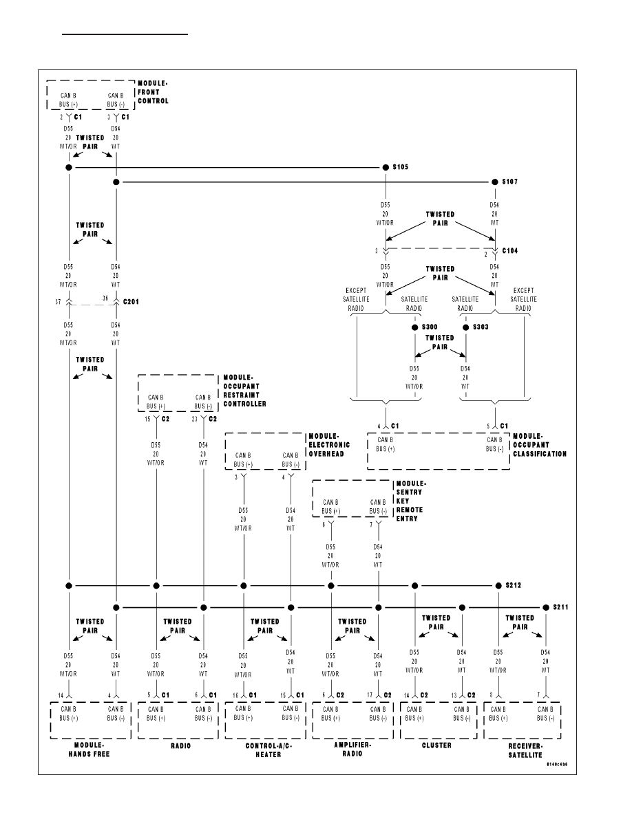
For a complete wiring diagram Refer to Section 8W.
•
When Monitored:
Continuously
•
Set Condition:
The FCM detects the (D54) CAN B Bus (-) circuit is shorted to ground.
Possible Causes
(D54) CAN B BUS (-) CIRCUIT SHORTED TO GROUND OR TO (D54) CAN B BUS (-) CIRCUIT
ANY CAN B BUS MODULE
FRONT CONTROL MODULE
Diagnostic Test
1.
TEST FOR INTERMITTENT CONDITION
Turn the ignition on.
With the scan tool, record and erase FCM DTC’s.
Cycle the ignition from on to off 3 times.
Turn the ignition on.
With the scan tool, read active FCM DTC’s.
Does the scan tool display this DTC as active?
Yes
>> Go To 2
No
>> The conditions that caused this code to set are not present at this time. Using the wiring diagram/sche-
matic as a guide, inspect the wiring and connectors.
2.
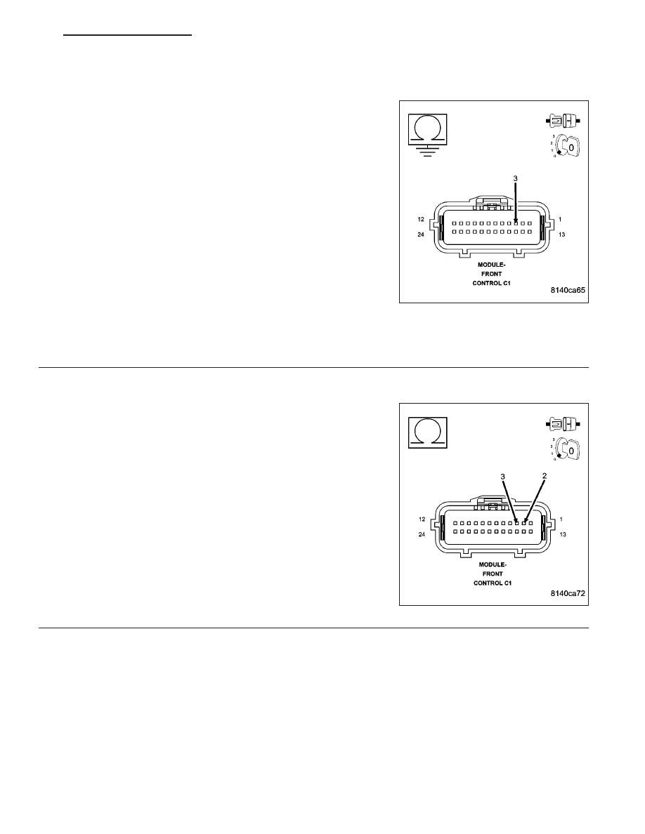
CHECK THE (D54) CAN B BUS (-) CIRCUIT FOR A SHORT TO GROUND
Turn the ignition off.
Disconnect the Front Control Module C1 harness connector.
Measure the resistance between ground and the (D54) CAN B Bus (-)
circuit.
Is resistance below 1000.0 ohms?
Yes
>> Go To 3
No
>> Go To 4
8E - 32
ELECTRONIC CONTROL MODULES - ELECTRICAL DIAGNOSTICS
ND
U0025-CAN B BUS (-) CIRCUIT LOW (CONTINUED)
3.
(D54) CAN B BUS (-) CIRCUIT SHORTED TO GROUND
Measure the resistance between ground and the (D54) CAN B Bus (-)
circuit.
While monitoring the ohmmeter, disconnect each CAN B Bus module
one at a time.
NOTE: This is to determine if the short to ground is internal
within a module or if the circuit is shorted.
NOTE: Disconnecting an in-line connector can eliminate a module
or group of modules from the list of possible causes for this
fault. Refer to the wring diagrams to assist in diagnosis.
Is resistance below 1000.0 ohms with all the CAN B Bus mod-
ules disconnected?
Yes
>> Repair the (D54) CAN B Bus (-) circuit for a short to
ground.
Perform BODY VERIFICATION TEST - VER 1. (Refer to
BODY VERIFICATION TEST - VER 1).
No
>> Replace the module that when disconnected the short to ground was eliminated, in accordance with the
service information.
Perform BODY VERIFICATION TEST - VER 1. (Refer to BODY VERIFICATION TEST - VER 1).
4.
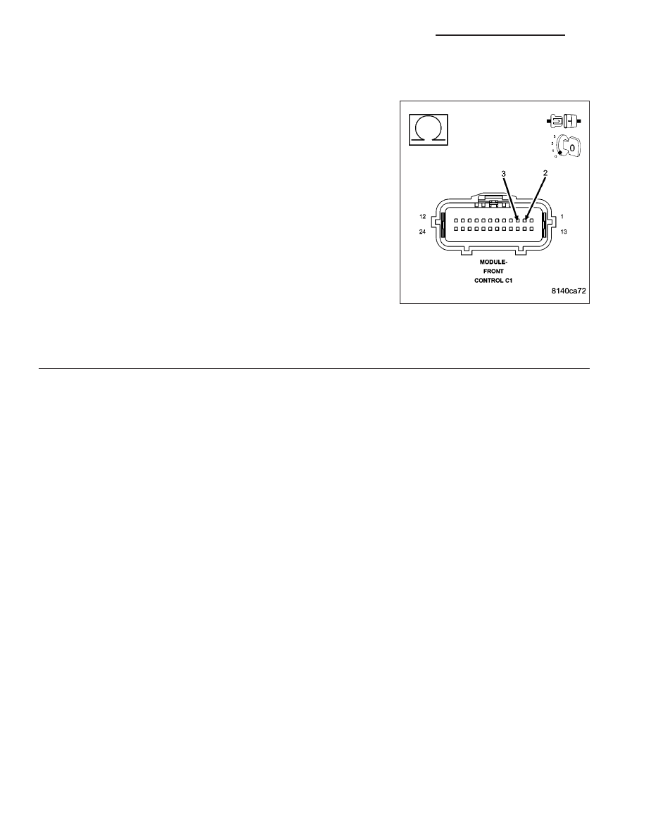
CHECK THE (D55) CAN B BUS (+) CIRCUIT FOR A SHORT TO THE (D54) CAN B BUS (-) CIRCUIT
Measure the resistance between the (D55) CAN B Bus (+) circuit and
(D54) CAN B Bus (-) circuit.
Is resistance below 1000.0 ohms?
Yes
>> Go To 5
No
>> Inspect the wiring and connectors for damage or shorted
circuits. If ok, replace the Front Control Module in accor-
dance with the service information.
Perform BODY VERIFICATION TEST - VER 1. (Refer to
BODY VERIFICATION TEST - VER 1).
ND
ELECTRONIC CONTROL MODULES - ELECTRICAL DIAGNOSTICS
8E - 33
U0025-CAN B BUS (-) CIRCUIT LOW (CONTINUED)
5.
(D55) CAN B BUS (+) CIRCUIT SHORTED TO THE (D54) CAN B BUS (-) CIRCUIT
Measure the resistance between the (D55) CAN B Bus (+) circuit and
(D54) CAN B Bus (-) circuit.
While monitoring the ohmmeter, disconnect each CAN B Bus module
one at a time.
NOTE: This is to determine if the short together is internal within
a module or if the circuits are shorted together.
NOTE: Disconnecting an in-line connector can eliminate a module
or group of modules from the list of possible causes for this
fault. Refer to the wring diagrams to assist in diagnosis.
Is resistance below 1000.0 ohms with all the CAN B Bus mod-
ules disconnected?
Yes
>> Repair the (D55) CAN B Bus (+) circuit for a short to the
(D54) CAN B Bus (-) circuit.
Perform BODY VERIFICATION TEST - VER 1. (Refer to
BODY VERIFICATION TEST - VER 1).
No
>> Replace the module that when disconnected the short to ground was eliminated, in accordance with the
service information.
Perform BODY VERIFICATION TEST - VER 1. (Refer to BODY VERIFICATION TEST - VER 1).
8E - 34
ELECTRONIC CONTROL MODULES - ELECTRICAL DIAGNOSTICS
ND
U0026-CAN B BUS (-) CIRCUIT HIGH
ND
ELECTRONIC CONTROL MODULES - ELECTRICAL DIAGNOSTICS
8E - 35
Нет комментариевНе стесняйтесь поделиться с нами вашим ценным мнением.
Текст