Dodge Dakota (ND). Manual — part 11
UPPER CONTROL ARM BUSHING
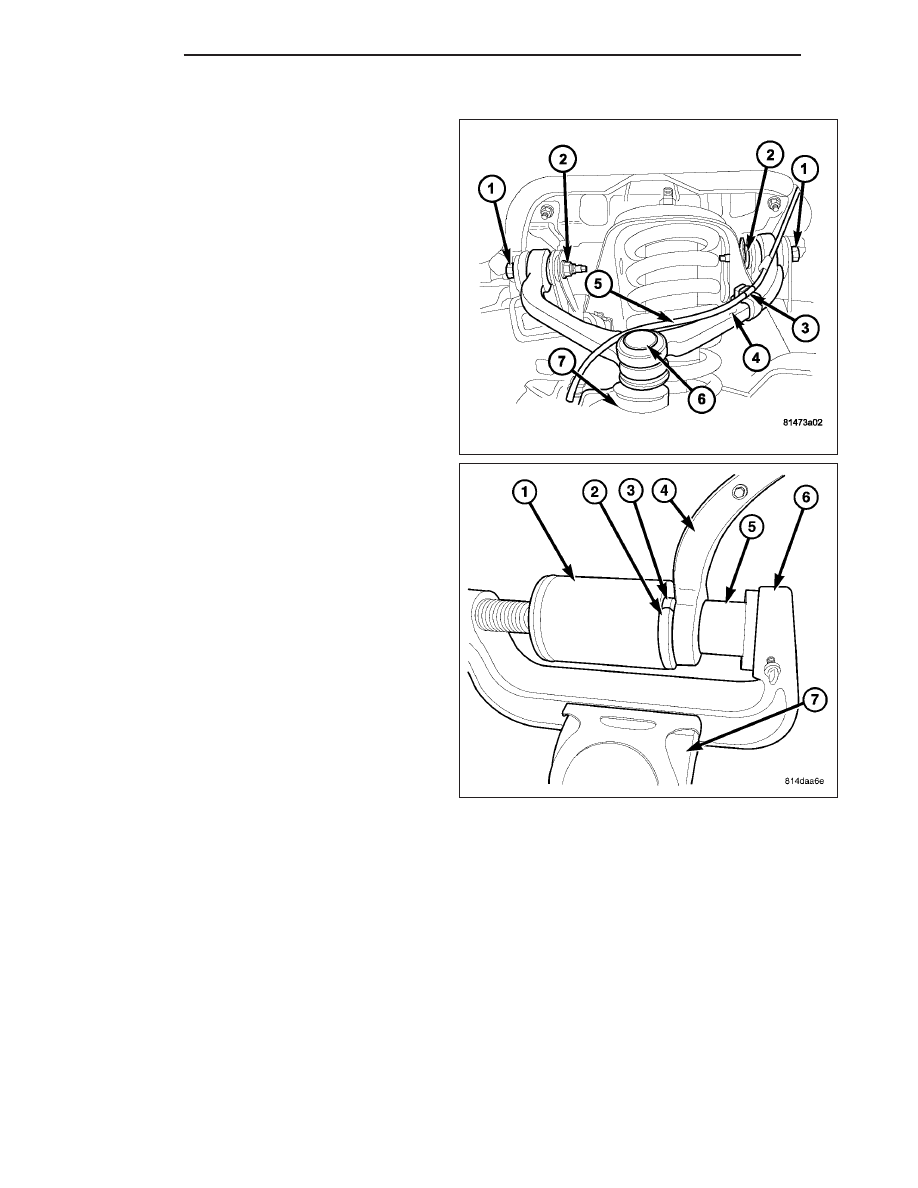
1. Remove the upper control arm (4) (Refer to 2 -
SUSPENSION/FRONT/UPPER CONTROL ARM -
REMOVAL).
2. Secure the control arm in a vise (7).
NOTE: Extreme pressure lubrication must be used
on the threaded portions of the tool. This will
increase the longevity of the tool and insure
proper operation during the removal and installa-
tion process.
3. Install
special
tools
C-4212-F
(press)
(6),
6761(Receiver) (1), 9601-2 (Reaction Plate) (2),
9601-1 (Driver) (5) to press the bushing (3) out of
the upper control arm (4).
2 - 12
FRONT
ND
LOWER CONTROL ARM SHOCK BUSHING
1. Remove the shock (Refer to 2 - SUSPENSION/
FRONT/SHOCK - REMOVAL).
NOTE: Extreme pressure lubrication must be used
on the threaded portions of the tool. This will
increase the longevity of the tool and insure
proper operation during the removal and installa-
tion process.
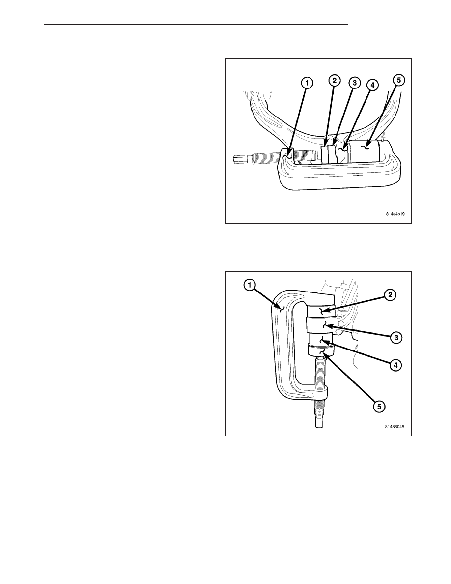
2. Install special tools to press the bushing (3) out of
the lower control arm (4) using special tools
C-4212-F (Press) (1), 9653–1 (driver) (4) and 9602
(Receiver) (5).
INSTALLATION
LOWER CONTROL ARM BUSHING
1. Install the new bushing (4) into the lower control
arm (3) using tools C-4212-F (Press) (1), 9603–2
(Depth Gauge) (2), 9603–1 (Driver) (5).
ND
FRONT
2 - 13
2. Remove the control arm from the vise.
3. Install the lower control arm (6) (Refer to 2 - SUS-
PENSION/FRONT/LOWER
CONTROL
ARM
-
INSTALLATION).
4. Reset the vehicle ride height (Refer to 2 - SUS-
PENSION/WHEEL
ALIGNMENT
-
STANDARD
PROCEDURE).
5. Perform a wheel alignment (Refer to 2 - SUSPEN-
SION/WHEEL
ALIGNMENT
-
STANDARD
PROCEDURE).
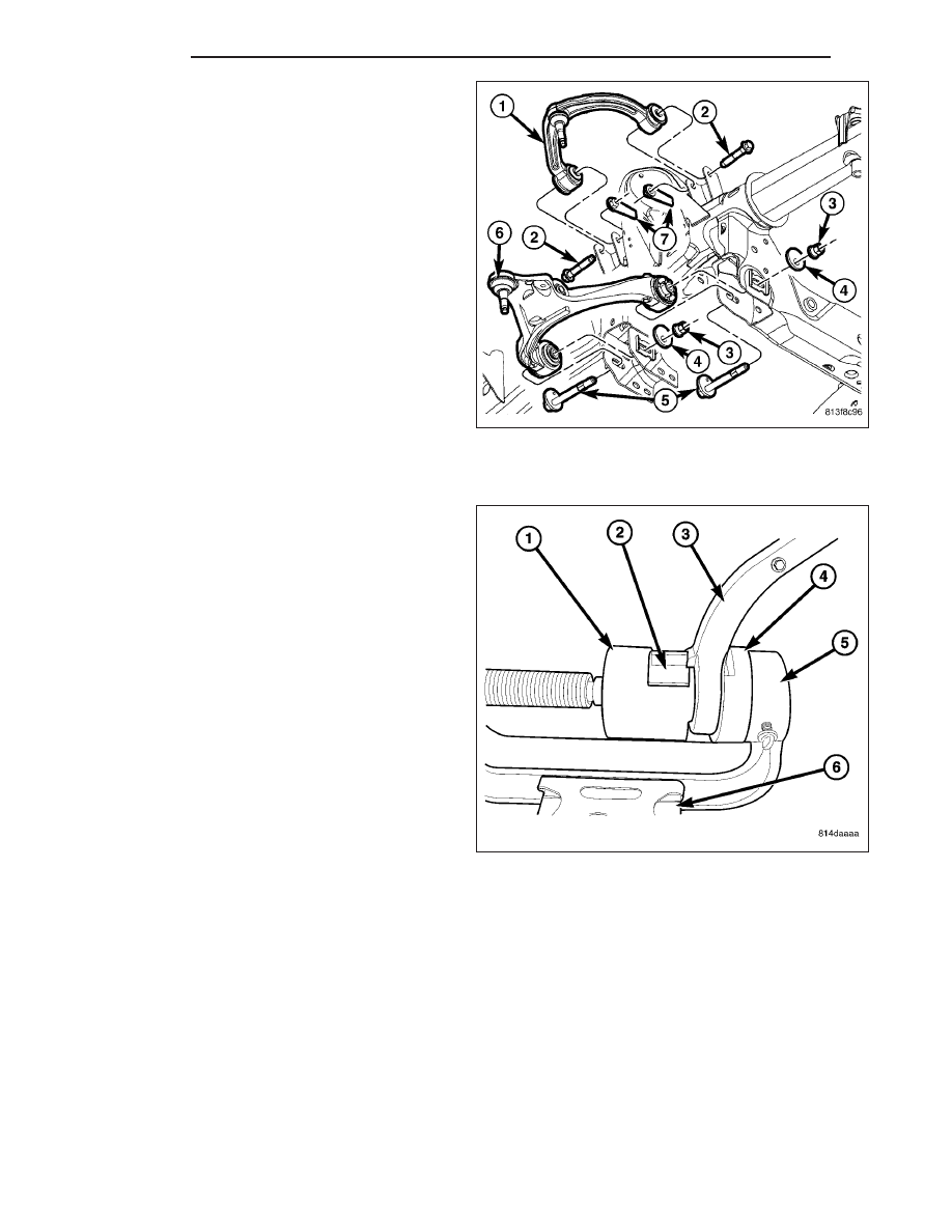
UPPER CONTROL ARM BUSHING
1. Install the new bushing (2) into the lower control (3)
arm using tools C-4212-F (Press) (5), 9601-3
(Depth Gauge) (4), 9601-4 (Driver) (1).
2. Remove the control arm from the vise (6).
2 - 14
FRONT
ND
3. Install the upper control arm (4) (Refer to 2 - SUS-
PENSION/FRONT/UPPER
CONTROL
ARM
-
INSTALLATION).
4. Reset the vehicle ride height (Refer to 2 - SUS-
PENSION/WHEEL
ALIGNMENT
-
STANDARD
PROCEDURE).
5. Perform a wheel alignment (Refer to 2 - SUSPEN-
SION/WHEEL
ALIGNMENT
-
STANDARD
PROCEDURE).
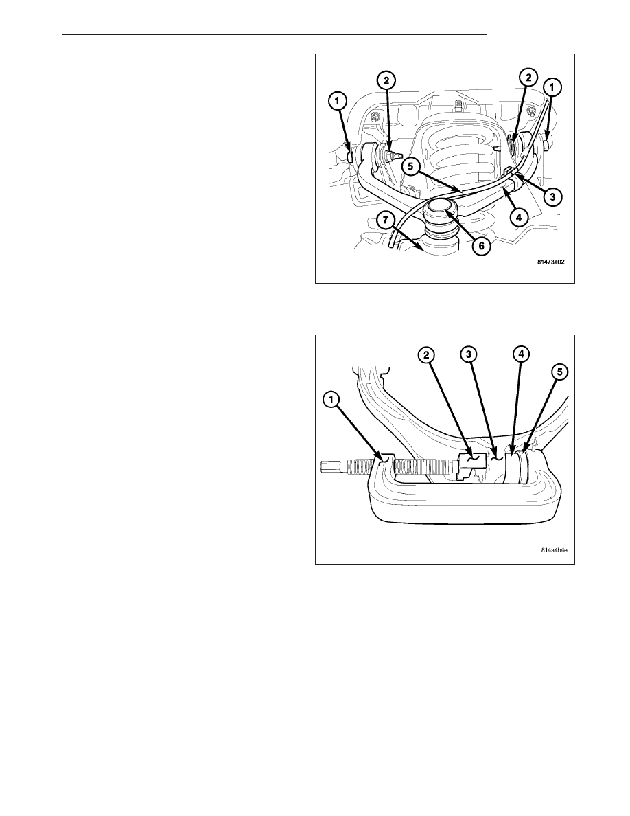
LOWER CONTROL ARM SHOCK BUSHING
NOTE: Extreme pressure lubrication must be used
on the threaded portions of the tool. This will
increase the longevity of the tool and insure
proper operation during the removal and installa-
tion process.
1. Install the new shock bushing (3) into the lower
control arm (3) using tools C-4212-F (Press) (1),
9653–3 (driver) (5), 9602–2 (Depth gauge) (2) the
depth gauge will automatically set the depth of the
bushing (4) in the control arm (3).
2. Install the shock (Refer to 2 - SUSPENSION/
FRONT/SHOCK - INSTALLATION).
HUB / BEARING
REMOVAL
1. Raise and support the vehicle.
2. Remove the wheel and tire assembly.
3. Remove the brake caliper and rotor (Refer to 5 - BRAKES/HYDRAULIC/MECHANICAL/ROTORS - REMOVAL).
4. Remove the ABS wheel speed sensor if equipped, (Refer to 5 - BRAKES/ELECTRICAL/FRONT WHEEL SPEED
SENSOR - REMOVAL).
5. Remove the halfshaft nut 4X4 only.
ND
FRONT
2 - 15
Нет комментариевНе стесняйтесь поделиться с нами вашим ценным мнением.
Текст