Dodge Dakota (ND). Manual — part 672
P0175-FUEL SYSTEM 2/1 RICH (CONTINUED)
2.
CHECKING FUEL PRESSURE
WARNING: The fuel system is under a constant pressure (even with the engine off). Before testing or ser-
vicing any fuel system hose, fitting or line, the fuel system pressure must be released. Failure to follow
these instructions can result in personal injury or death.
Install a fuel pressure gauge to the fuel rail.
Ignition on, engine not running.
With the scan tool, actuate the ASD Fuel System test and observe the fuel pressure gauge.
NOTE: Fuel pressure specification is 407 KPa +/- 34 KPa (59 psi +/- 5 psi).
Turn the ignition off.
CAUTION: Stop All Actuations.
Choose a conclusion that best matches your fuel pressure reading.
Within Specification
Go To 3
Above Specification
Replace the fuel filter/pressure regulator.
Perform POWERTRAIN VERIFICATION TEST. (Refer to 9 - ENGINE - STANDARD PROCEDURE)
3.
O2 SENSOR OPERATION
Start the engine.
Allow the engine to reach normal operating temperature.
NOTE: If one of the O2 Sensors Signal or Return circuit is shorted to ground or voltage, all the other O2
Sensor voltage readings will be affected.
NOTE: After the repairs have been made, verify proper O2 Sensor operation. If all the O2 Sensor voltage
readings have not returned to normal, follow the diagnostic procedure for the remaining O2 Sensors.
With the scan tool, monitor the 2/1 O2 Sensor voltage reading.
Is the voltage switching between 2.5 and 3.4 volts?
Yes
>> Go To 4
No
>> Go To 9
4.
2/1 O2 SENSOR HEATER OPERATION
Turn the ignition off.
NOTE: Wait a minimum of 10 minutes to allow the O2 Sensor to cool down before continuing the test. Allow
the O2 Sensor voltage to stabilize at 5.0 volts.
Ignition on, engine not running.
With the scan tool, perform the 2/1 O2 Heater Test for each O2 Sensor.
With the scan tool, monitor the 2/1 O2 Sensor voltage while performing the Heater test for at least 2 minutes.
Does the voltage stay above 4.5 volts for each Sensor?
Yes
>> Replace the 2/1 O2 Sensor.
Perform POWERTRAIN VERIFICATION TEST. (Refer to 9 - ENGINE - STANDARD PROCEDURE)
No
>> Go To 5
9 - 226
ENGINE ELECTRICAL DIAGNOSTICS
ND
P0175-FUEL SYSTEM 2/1 RICH (CONTINUED)
5.
MAP SENSOR OPERATION
Turn the ignition off.
Connect a Vacuum Gauge to a Manifold Vacuum source.
Start the engine.
Allow the engine to idle.
NOTE: If engine will not idle, maintain a constant RPM above idle.
With the scan tool, read the MAP Sensor vacuum value.
Is the scan tool reading within 1
(
of the Vacuum Gauge reading?
Yes
>> Go To 6
No
>> Replace the MAP Sensor.
Perform POWERTRAIN VERIFICATION TEST. (Refer to 9 - ENGINE - STANDARD PROCEDURE)
NOTE: Remove the vacuum gauge before continuing.
6.
ECT SENSOR OPERATION
NOTE: For this test to be valid, the thermostat must be operating correctly.
NOTE: This test works best if performed on a cold engine (cold soak).
Ignition on, engine not running.
With the scan tool, read the Engine Coolant Temperature Sensor value. If the engine was allowed to sit overnight
(cold soak), the temperature value should be a sensible value that is somewhere close to the ambient temperature.
NOTE: If engine coolant temperature is above 82°C (180°F), allow the engine to cool until 65°C (150°F) is
reached.
Start the Engine.
During engine warm-up, monitor the Engine Coolant Temperature value. The temp value change should be a
smooth transition from start up to normal operating temp 82°C (180°F). The value should reach at least 82°C
(180°F).
Did the ECT value increase smoothly and reach at least 180°F (82°C)?
Yes
>> Go To 7
No
>> Replace the Engine Coolant Temperature Sensor.
Perform POWERTRAIN VERIFICATION TEST. (Refer to 9 - ENGINE - STANDARD PROCEDURE)
7.
EVAP PURGE SOLENOID OPERATION
Turn the ignition off.
Disconnect the hoses at the Evap Purge Solenoid.
Using a hand vacuum pump, apply 10 inches of vacuum to the Evap Purge Solenoid vacuum source port on the
component side.
Did the Evap Purge Solenoid hold vacuum?
Yes
>> Go To 8
No
>> Replace the EVAP Purge Solenoid.
Perform POWERTRAIN VERIFICATION TEST. (Refer to 9 - ENGINE - STANDARD PROCEDURE)
NOTE: Connect the vacuum hoses before continuing.
ND
ENGINE ELECTRICAL DIAGNOSTICS
9 - 227
P0175-FUEL SYSTEM 2/1 RICH (CONTINUED)
8.
ENGINE MECHANICAL
Check for any of the following conditions/mechanical problems.
AIR INDUCTION SYSTEM - must be free from restrictions.
ENGINE VACUUM - must be at least 13 inches in neutral
ENGINE VALVE TIMING - must be within specifications
ENGINE COMPRESSION - must be within specifications
ENGINE EXHAUST SYSTEM - must be free of any restrictions or leaks.
ENGINE PCV SYSTEM - must flow freely
TORQUE CONVERTER STALL SPEED - must be within specifications
POWER BRAKE BOOSTER - no internal vacuum leaks
FUEL - must be free of contamination
FUEL INJECTOR - plugged or restricted injector; control wire not connected to correct injector
Are there any engine mechanical problems?
Yes
>> Repair as necessary.
Perform POWERTRAIN VERIFICATION TEST. (Refer to 9 - ENGINE - STANDARD PROCEDURE)
No
>> Go To 12
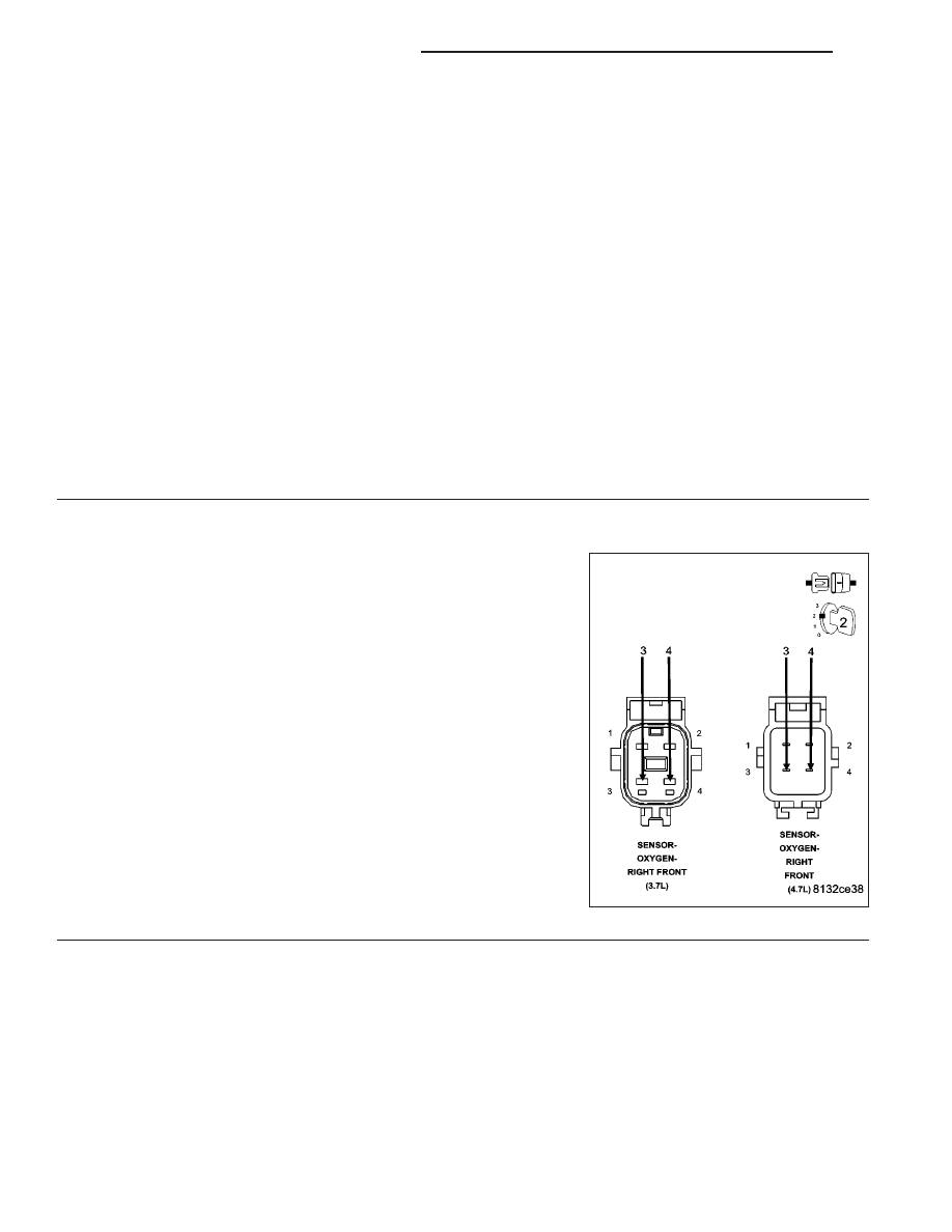
9.
2/1 O2 SENSOR
Ignition on, engine not running.
Disconnect the 2/1 O2 Sensor harness connector.
With the scan tool, monitor the 2/1 O2 Sensor voltage.
O2 Sensor voltage should read 5.0 volts on the scan tool with the con-
nector disconnected.
Connect a jumper wire between the (K43) O2 Sensor 2/1 Signal circuit
and the (K902) O2 Return Upstream circuit in the O2 Sensor harness
connector.
NOTE: The voltage should drop from 5.0 volts down to 2.5 volts
with the jumper wire connected.
Did the O2 Sensor voltage drop from 5 volts to 2.5 volts when
the jumper wire was installed?
Yes
>> Replace the O2 Sensor
Perform POWERTRAIN VERIFICATION TEST. (Refer to 9
- ENGINE - STANDARD PROCEDURE)
No
>> Go To 10
NOTE: Remove the jumper wire before continuing.
9 - 228
ENGINE ELECTRICAL DIAGNOSTICS
ND
P0175-FUEL SYSTEM 2/1 RICH (CONTINUED)
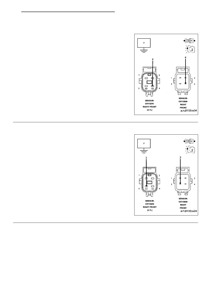
10.
O2 SENSOR SIGNAL CIRCUIT
WARNING: When the engine is operating, do not stand in direct
line with the fan. Do not put your hands near the pulleys, belts, or
fan. Do not wear loose clothing. Failure to follow these instruc-
tions can result in personal injury or death.
Start the engine.
Measure the voltage on the (K43) O2 Sensor 2/1 Signal circuit in the
O2 Sensor harness connector.
Is the voltage above 4.8 volts?
Yes
>> Check the (K43) O2 Sensor 2/1 Signal circuit for damage,
short to ground, open, or short to voltage. Inspect the O2
Sensor connector and the PCM harness connector. If OK,
replace and program the Powertrain Control Module per
Service Information.
Perform POWERTRAIN VERIFICATION TEST. (Refer to 9
- ENGINE - STANDARD PROCEDURE)
No
>> Go To 11
11.
(K902) O2 SENSOR RETURN UPSTREAM CIRCUIT
Engine still running.
Measure the voltage on the (K902) O2 Return Upstream circuit in the
O2 Sensor harness connector.
Is the voltage at 2.5 volts?
Yes
>> Go To 12
No
>> Check the (K902) O2 Return Upstream circuit for damage,
short to ground, open, or short to voltage. Inspect the O2
Sensor connector and the PCM harness connector. If OK,
replace and program the Powertrain Control Module per
Service Information.
Perform POWERTRAIN VERIFICATION TEST. (Refer to 9
- ENGINE - STANDARD PROCEDURE)
NOTE: Turn the ignition off before continuing.
ND
ENGINE ELECTRICAL DIAGNOSTICS
9 - 229
Нет комментариевНе стесняйтесь поделиться с нами вашим ценным мнением.
Текст