Dodge Dakota (ND). Manual — part 530
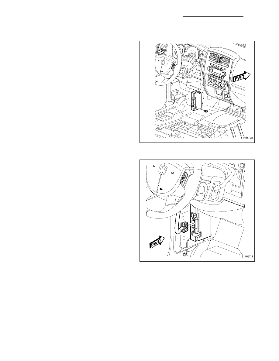
INSTALLATION
1. Position
module.
Install
and
tighten
mounting
fasteners.
2. Connect electrical harness connector.
3. Install cowl side trim panel.
4. Connect battery negative cable.
8T - 60
NAVIGATION/TELECOMMUNICATION - SERVICE INFORMATION
ND
WIRING
TABLE OF CONTENTS
page
page
LOCATION . . . . . . . . . . . . . . . . . . . . . . . . 8W-91-1
INFORMATION . . . . . . . . . . . . . . . . . . . . . 8W-97-1
ND
WIRING
8W - 1
8W-01 WIRING DIAGRAM INFORMATION
TABLE OF CONTENTS
page
page
WIRING DIAGRAM INFORMATION
DESCRIPTION - HOW TO USE WIRING
DIAGRAMS . . . . . . . . . . . . . . . . . . . . . . . . . . . 1
DESCRIPTION - CIRCUIT INFORMATION
DESCRIPTION - CIRCUIT FUNCTIONS
DESCRIPTION - SECTION IDENTIFICATION
AND INFORMATION . . . . . . . . . . . . . . . . . . . . 6
DESCRIPTION - CONNECTOR, GROUND
AND SPLICE INFORMATION . . . . . . . . . . . . . . 7
. . . . . . . . . . . . . . . . . 7
DIAGNOSIS AND TESTING - WIRING
. . . . . . . . . . . . . . . . . . . . . . . . . . . . 8
ELECTROSTATIC DISCHARGE (ESD)
SENSITIVE DEVICES . . . . . . . . . . . . . . . . . . . 9
STANDARD PROCEDURE - TESTING OF
VOLTAGE POTENTIAL . . . . . . . . . . . . . . . . . . 10
STANDARD PROCEDURE - TESTING FOR
CONTINUITY . . . . . . . . . . . . . . . . . . . . . . . . . 10
STANDARD PROCEDURE - TESTING FOR A
SHORT TO GROUND . . . . . . . . . . . . . . . . . . . 10
STANDARD PROCEDURE - TESTING FOR A
SHORT TO GROUND ON FUSES
POWERING SEVERAL LOADS . . . . . . . . . . . . 11
STANDARD PROCEDURE - TESTING FOR A
VOLTAGE DROP . . . . . . . . . . . . . . . . . . . . . . 11
. . . . . . . . . . . . . . . . . . . . 12
CONNECTOR
. . . . . . . . . . . . . . . . . . . . . . . . . . . . . 13
. . . . . . . . . . . . . . . . . . . . . . . . . 15
DIODE
. . . . . . . . . . . . . . . . . . . . . . . . . . . . . 16
. . . . . . . . . . . . . . . . . . . . . . . . . 16
TERMINAL
. . . . . . . . . . . . . . . . . . . . . . . . . . . . . 16
. . . . . . . . . . . . . . . . . . . . . . . . . 16
WIRE
STANDARD PROCEDURE - WIRE SPLICING
WIRING DIAGRAM INFORMATION
DESCRIPTION
DESCRIPTION - HOW TO USE WIRING DIAGRAMS
DaimlerChrysler Corporation wiring diagrams are designed to provide information regarding the vehicles wiring con-
tent. In order to effectively use the wiring diagrams to diagnose and repair DaimlerChrysler Corporation vehicles, it
is important to understand all of their features and characteristics.
Diagrams are arranged such that the power (B+) side of the circuit is placed near the top of the page, and the
ground (B-) side of the circuit is placed near the bottom of the page.
All switches, components, and modules are shown in the at rest position with the doors closed and the key
removed from the ignition.
Components are shown two ways. A solid line around a component indicates that the component is complete. A
dashed line around the component indicates that the component is being shown is not complete. Incomplete com-
ponents have a reference number to indicate the page where the component is shown complete.
It is important to realize that no attempt is made on the diagrams to represent components and wiring as they
appear on the vehicle. For example, a short piece of wire is treated the same as a long one. In addition, switches
and other components are shown as simply as possible, with regard to function only.
SYMBOLS
International symbols are used throughout the wiring diagrams. These symbols are consistent with those being used
around the world.
ND
8W-01 WIRING DIAGRAM INFORMATION
8W - 01 - 1
Нет комментариевНе стесняйтесь поделиться с нами вашим ценным мнением.
Текст