Dodge Dakota (ND). Manual — part 153
B1462-CHANNEL 1 AUDIO SPEAKER OUTPUT CIRCUIT HIGH (CONTINUED)
3.
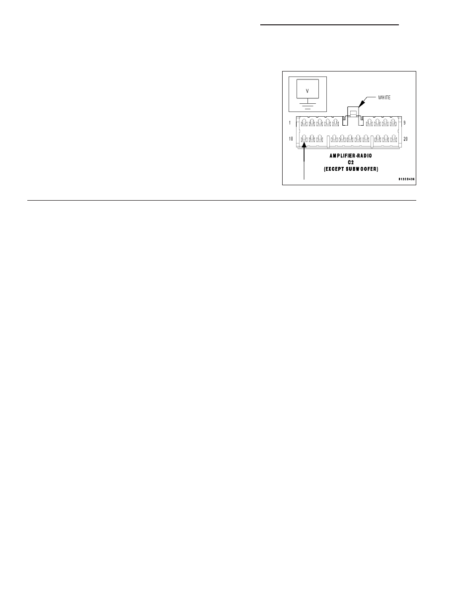
CHECK FOR VOLTAGE ON THE (X299) AMPLIFIED LEFT I/P SPEAKER (-) CIRCUIT
Measure for voltage on the (X299) Amplified Left I/P Speaker (-) cir-
cuit.
Is the voltage above 10.0 volts?
Yes
>> Repair the (X299) Amplified Left I/P Speaker (-) circuit for
a short to voltage.
Perform BODY VERIFICATION TEST VER-1.
No
>> Replace the Amplifier in accordance with the service infor-
mation.
Perform BODY VERIFICATION TEST VER-1.
8A - 70
AUDIO/VIDEO SYSTEMS - ELECTRICAL DIAGNOSIS
ND
B1463-CHANNEL 1 AUDIO SPEAKER OUTPUT CIRCUIT OPEN
ND
AUDIO/VIDEO SYSTEMS - ELECTRICAL DIAGNOSIS
8A - 71
B1463-CHANNEL 1 AUDIO SPEAKER OUTPUT CIRCUIT OPEN (CONTINUED)
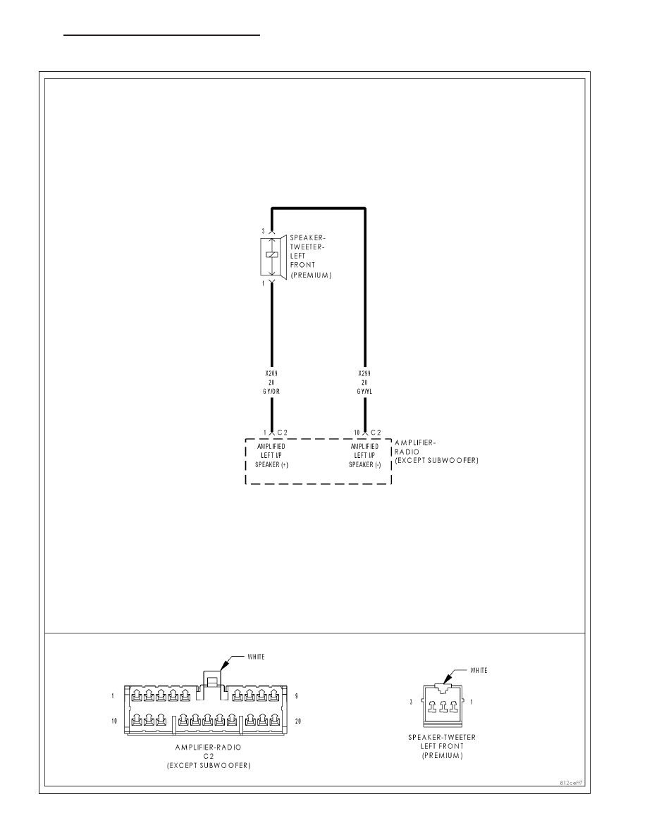
For the Amplifier circuit diagram (Refer to 8 - ELECTRICAL/AUDIO - SCHEMATICS AND DIAGRAMS).
For a complete wiring diagram Refer to Section 8W.
•
When Monitored:
Amplifier Bus wake-up. Amplifier reset with scan tool.
•
Set Condition:
The Amplifier detects an open condition on the speaker output circuit.
Possible Causes
(X209) AMPLIFIED LEFT I/P SPEAKER (+) CIRCUIT OPEN
(X299) AMPLIFIED LEFT I/P SPEAKER (-) CIRCUIT OPEN
LEFT FRONT I/P SPEAKER
AMPLIFIER
Diagnostic Test
1.
CHECK FOR AN INTERMITTENT CONDITION
Turn the ignition on.
Turn the radio on.
With the scan tool, erase Amplifier DTCs.
With the scan tool, reset the amplifier.
With the scan tool, read Amplifier DTCs.
Does the scan tool display active: B1463-CHANNEL 1 AUDIO
SPEAKER OUTPUT CIRCUIT OPEN?
Yes
>> Go To 2
No
>> The conditions that caused this code to set are not
present at this time. Using the wiring diagram/schematic
as a guide, inspect the wiring and connectors.
Perform BODY VERIFICATION TEST VER-1.
2.
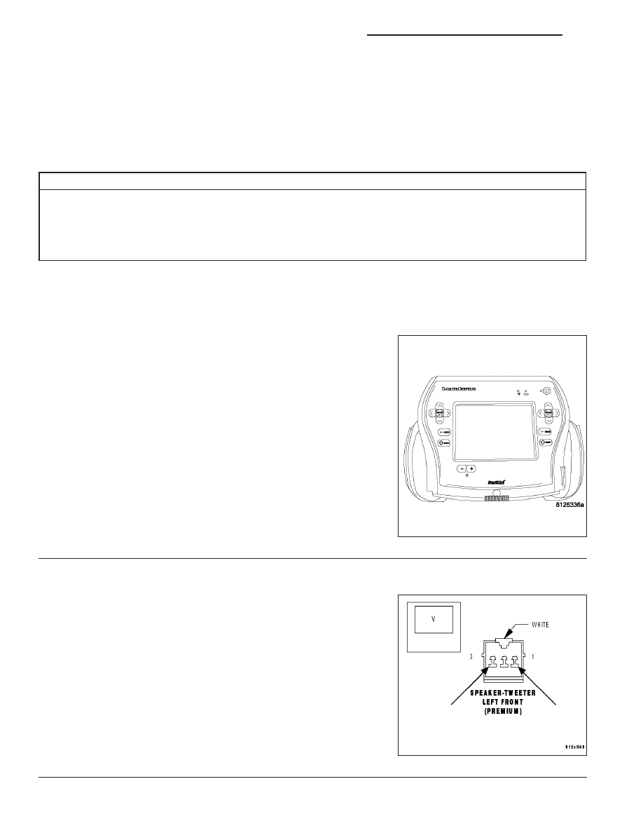
CHECK THE OPERATION OF THE LEFT FRONT I/P SPEAKER
Disconnect the Left I/P Speaker harness connector.
Turn the radio on and turn the volume to mid level.
With a voltmeter set to read in A/C voltage, measure the voltage of the
Amplified Left I/P Speaker circuits in the Amplified Left I/P Speaker
harness connector.
Is the voltage present greater than 1 volt?
Yes
>> Replace the Amplified Left I/P Speaker in accordance with
the service information.
Perform BODY VERIFICATION TEST VER-1.
No
>> Go To 3
8A - 72
AUDIO/VIDEO SYSTEMS - ELECTRICAL DIAGNOSIS
ND
B1463-CHANNEL 1 AUDIO SPEAKER OUTPUT CIRCUIT OPEN (CONTINUED)
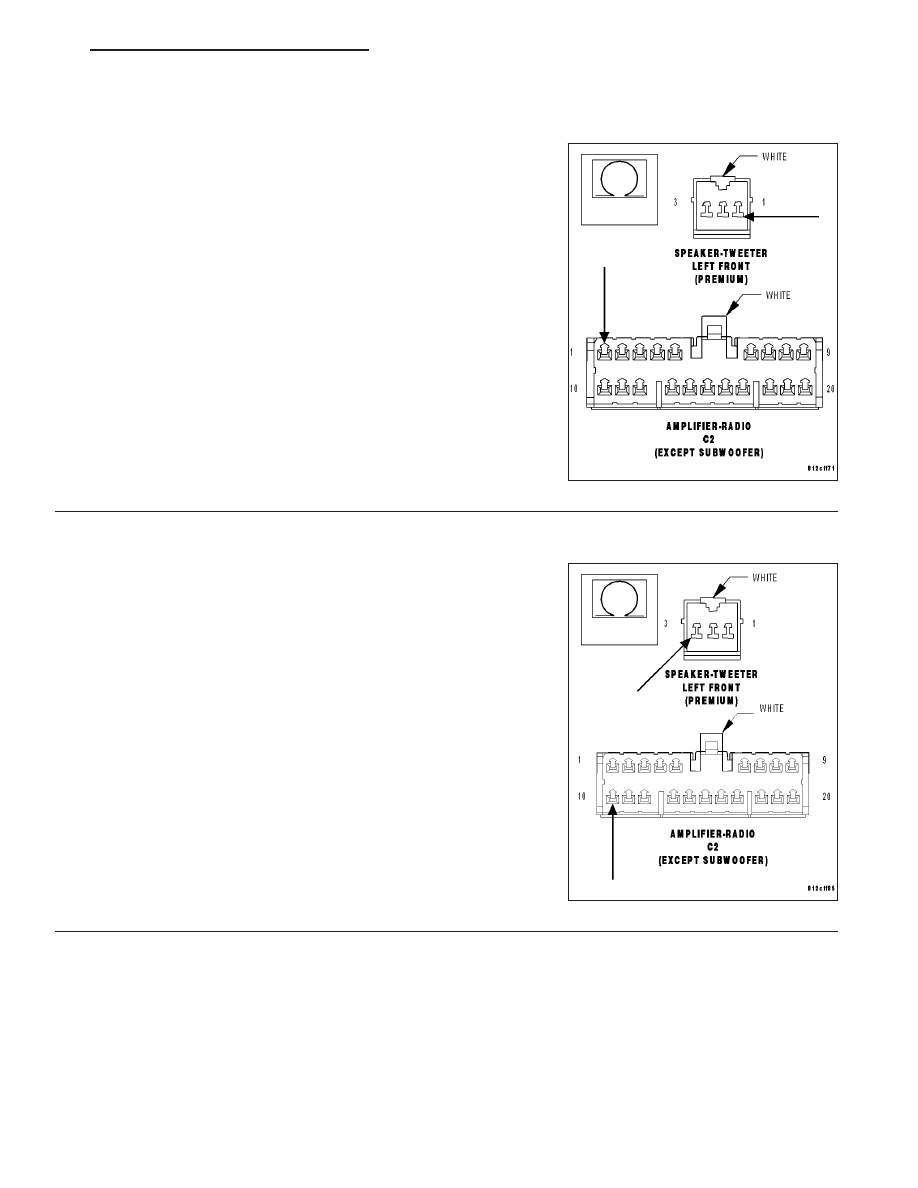
3.
CHECK THE (X209) AMPLIFIED LEFT I/P SPEAKER (+) CIRCUIT FOR AN OPEN
Turn the ignition off.
Disconnect the Amplifier C2 harness connector.
Measure the resistance of the (X209) Amplified Left I/P Speaker (+)
circuit between the Amplifier C2 harness connector and the Amplified
Left I/P Speaker harness connector.
Is the resistance below 5.0 ohms?
Yes
>> Go To 4
No
>> Repair the (X209) Amplified Left I/P Speaker (+) circuit for
an open.
Perform BODY VERIFICATION TEST VER-1.
4.
CHECK THE (X299) AMPLIFIED LEFT I/P SPEAKER (-) CIRCUIT FOR AN OPEN
Turn the ignition off.
Disconnect the Amplifier C2 harness connector.
Measure the resistance of the (X299) Amplified Left I/P Speaker (-) cir-
cuit between the Amplifier C2 harness connector and the Amplified
Left I/P Speaker harness connector.
Is the resistance below 5.0 ohms?
Yes
>> Replace the Amplifier in accordance with the service infor-
mation.
Perform BODY VERIFICATION TEST VER-1.
No
>> Repair the (X299) Amplified Left I/P Speaker (-) circuit for
an open.
Perform BODY VERIFICATION TEST VER-1.
ND
AUDIO/VIDEO SYSTEMS - ELECTRICAL DIAGNOSIS
8A - 73
Нет комментариевНе стесняйтесь поделиться с нами вашим ценным мнением.
Текст