Dodge Dakota (ND). Manual — part 1278
2. Connect a tachometer and a manifold gauge set.
NOTE: The ambient air temperature of the vehicle and the location where the vehicle will be tested must be
a minimum of 21° C (70° F) before performing this test. Also the evaporator temperature sensor probe
(located between the evaporator fins) must be a minimum of 18° C (65° F) for this test as well. If the vehicle
has been sitting in the sun prior to testing, place the vehicle in the testing area until the temperature within
the vehicle reaches a minimum of 18° C (65° F).
3. Set the A/C-heater control to the Recirculation mode (max-A/C) position, the temperature control to the full cool
position, and the blower motor control to the highest speed position.
4. Start the engine and hold the idle at 1,000 rpm with the compressor clutch engaged. If the A/C compressor does
not engage, see the A/C Pressure Diagnosis chart.
5. The engine should be at operating temperature and the doors and the windows closed.
6. Insert a thermometer in the driver side center panel outlet. Operate the A/C system until it stabilizes.
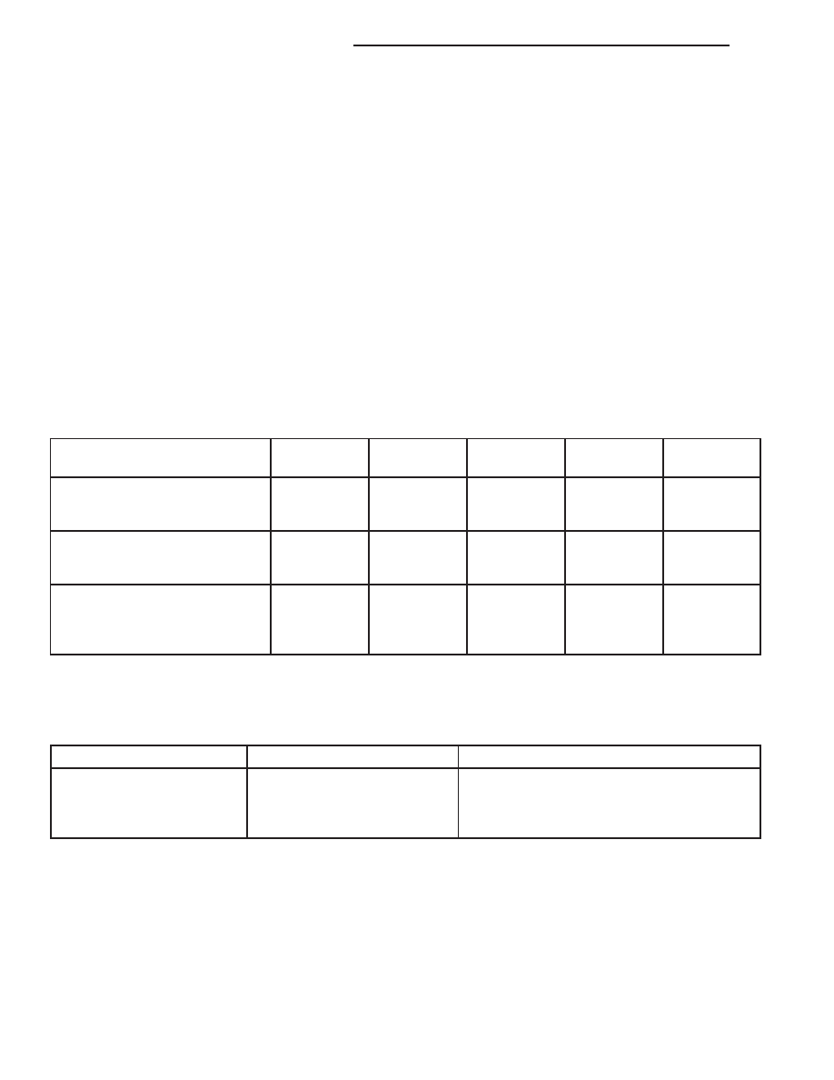
7. With the A/C compressor clutch engaged, compare the air temperature at the center panel outlet and the com-
pressor discharge pressure (high side) to the A/C Performance and Pressure chart. The compressor clutch may
cycle, depending upon the ambient temperature and humidity. If the clutch cycles, use the readings obtained
before the clutch disengaged.
A/C PERFORMANCE TEMPERATURE AND PRESSURE
Ambient Air Temperature
21°C
(70°F)
27°C
(80°F)
32°C
(90°F)
38°C
(100°F)
43°C
(110°F)
Maximum Allowable Air
Temperature at Center Panel
Outlet
9°C
(48°F)
9°C
(48°F)
12°C
(54°F)
15°C
(59°F)
18°C
(65°F)
Suction Pressure at Service
Port (Low Side)
138 to 310
kPa
(20 to 45 psi)
138 to 345
kPa
(20 to 50 psi)
207 to 365
kPa
(30 to 55 psi)
207 to 414
kPa
(30 to 60 psi)
241 to 448
kPa
(35 to 65 psi)
Discharge Pressure at Service
Port (High Side)
1034 to 1724
kPa
(150 to 250
psi)
1379 to 2068
kPa
(200 to 300
psi)
1551 to 2241
kPa
(225 to 325
psi)
1724 to 2413
kPa
(250 to 350
psi)
2068 to 2758
kPa
(300 to 400
psi)
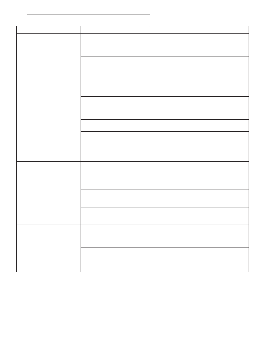
8. If the air outlet temperature fails to meet the specifications in the A/C Performance Temperature and Pressure
chart, or if the compressor discharge pressure is high, refer to the A/C Pressure Diagnosis chart.
A/C PRESSURE DIAGNOSIS
Condition
Possible Causes
Correction
Rapid A/C compressor clutch
cycling with poor panel outlet
temperatures.
1. Low refrigerant system
charge.
1. See Refrigerant System Leaks in this group.
Test the refrigerant system for leaks. Repair,
evacuate and charge the refrigerant system, if
required.
24 - 110
HVAC - SERVICE INFORMATION
ND
Condition
Possible Causes
Correction
Equal pressures, but the
compressor clutch does not
engage.
1. No refrigerant in the
refrigerant system.
1. See Refrigerant System Leaks in this group.
Test the refrigerant system for leaks. Repair,
evacuate and charge the refrigerant system, if
required.
2. Faulty fuse.
2. Check the fuses in the Integrated Power
Module. Repair the shorted circuit or
component and replace the fuses, if required.
Refer to Group 8.
3. Faulty A/C compressor
clutch coil.
3. See A/C Compressor Clutch Coil in this
group. Test the compressor clutch coil and
replace, if required.
4. Faulty A/C compressor
clutch relay.
4. See A/C Compressor Clutch Relay in this
group. Test the compressor clutch relay and
relay circuits. Repair the circuits or replace the
relay, if required.
5. Improperly installed or faulty
evaporator temperature sensor.
5. See Evaporator Temperature Sensor in this
group. Test the sensor and replace, if required.
6. Faulty A/C pressure
transducer.
6. See A/C Pressure Transducer in this group.
Test the sensor and replace, if required.
7. Faulty Powertrain Control
Module (PCM).
7. Refer to Group 9 - Engine Electrical
Diagnostics for testing of the PCM. Test the
PCM and replace, if required.
Normal pressures, but A/C
Performance Test air
temperatures at center panel
outlet are too high.
1. Excessive refrigerant oil in
system.
1. See Refrigerant Oil Level in this group.
Recover the refrigerant from the refrigerant
system and inspect the refrigerant oil content.
Restore the refrigerant oil to the proper level, if
required.
2. Blend door actuator
improperly installed or faulty.
2. See Blend Door Actuator in this group.
Inspect the actuator for proper operation and
replace, if required.
3. Blend door inoperative or
sealing improperly.
3. See HVAC Housing in this group. Inspect
the blend door for proper operation and
sealing. Repair if required.
The low side pressure is
normal or slightly low, and the
high side pressure is too low.
1. Low refrigerant system
charge.
1. See Refrigerant System Leaks in this group.
Test the refrigerant system for leaks. Repair,
evacuate and charge the refrigerant system, if
required.
2. Refrigerant flow through the
A/C evaporator is restricted.
2. See A/C Evaporator in this group. Replace
the restricted A/C evaporator, if required.
3. Faulty A/C compressor.
3. See A/C Compressor in this group. Replace
the compressor, if required.
ND
HVAC - SERVICE INFORMATION
24 - 111

Condition
Possible Causes
Correction
The low side pressure is
normal or slightly high, and
the high side pressure is too
high.
1. A/C condenser air flow
restricted.
1. Check the A/C condenser for damaged fins,
foreign objects obstructing air flow through the
condenser fins, and missing or improperly
installed air seals. Clean, repair, or replace
components as required.
2. Refrigerant flow through the
accumulator is restricted.
2. See Accumulator in this group. Replace the
restricted accumulator, if required.
3. Inoperative radiator cooling
fan.
3. Test the radiator cooling fan and replace, if
required. Refer to Group 7.
4. Refrigerant system
overcharged.
4. See Refrigerant System Charge in this
group. Recover the refrigerant from the
refrigerant system. Charge the refrigerant
system to the proper level, if required.
5. Air in the refrigerant system.
5. See Refrigerant System Leaks in this group.
Test the refrigerant system for leaks. Repair,
evacuate and charge the refrigerant system, if
required.
6. Engine overheating.
6. Test the engine cooling system and repair, if
required. Refer to Group 7.
The low side pressure is too
high, and the high side
pressure is too low.
1. Accessory drive belt slipping.
1. Inspect the accessory drive belt condition
and tension. Tighten or replace the accessory
drive belt, if required. Refer to Group 7.
2. Faulty A/C orifice tube.
2. See A/C Orifice Tube in this group. Replace
the orifice tube, if required.
3. Faulty A/C compressor.
3. See A/C Compressor in this group. Replace
the compressor, if required.
The low side pressure is too
low, and the high side
pressure is too high.
1. Restricted refrigerant flow
through the refrigerant lines.
1. See Liquid Line, Suction Line and Discharge
Line in this group. Inspect the refrigerant lines
for kinks, tight bends or improper routing.
Correct the routing or replace the refrigerant
lines, as required.
2. Restricted refrigerant flow
through the A/C orifice tube.
2. See A/C Orifice Tube in this group. Replace
the orifice tube, if required.
3. Restricted refrigerant flow
through the A/C condenser.
3. See A/C Condenser in this group. Replace
the restricted condenser, if required.
HEATER PERFORMANCE
Before performing the following tests, refer to Group 7 - Cooling System for the procedures to check the engine
coolant level and flow, engine coolant reserve/recovery system operation, accessory drive belt condition and ten-
sion, radiator air flow and the fan drive operation. Perform the A/C System Performance Test, which is found within
the HVAC System Test (refer to 24 - HVAC Electrical Diagnostics). If any diagnostic trouble codes (DTCs) are found
in the A/C-heater control or the powertrain control module (PCM), repair as necessary.
HEATER PERFORMANCE TEST
Engine coolant is delivered to the heater core through two heater hoses. With the engine idling at normal operating
temperature, set the temperature control to the full hot position, the mode control to the floor position, and the
blower motor control to the highest speed position. Using a test thermometer, check the temperature of the air being
discharged at the HVAC housing floor outlets. Compare the test thermometer reading to the Heater Temperature
Reference chart.
24 - 112
HVAC - SERVICE INFORMATION
ND

HEATER TEMPERATURE REFERENCE
Ambient Air Temperature
15.5° C
(60° F)
21.1° C
(70° F)
26.6° C
(80° F)
32.2° C
(90° F)
Minimum Heater System Air
Outlet Temperature
52.2° C
(126° F)
56.1° C
(133° F)
59.4° C
(139° F)
62.2° C
(144° F)
If the heater outlet air temperature is below the minimum specification, refer to Group 7 - Cooling System. Both of
the heater hoses should be hot to the touch. The coolant return heater hose should be slightly cooler than the
coolant supply heater hose. If the return hose is much cooler than the supply hose, locate and repair the engine
coolant flow obstruction in the cooling system. Refer to Group 7 - Cooling System for more information.
OBSTRUCTED COOLANT FLOW
•
Faulty water pump.
•
Faulty thermostat.
•
Pinched or kinked heater hoses.
•
Improper heater hose routing.
•
Plugged heater hoses or supply and return ports at the cooling system connections.
•
A plugged heater core.
If proper coolant flow through the cooling system is verified, and heater outlet air temperature is still low, a mechan-
ical problem may exist.
MECHANICAL PROBLEMS
Possible locations or causes of insufficient heat:
•
Obstructed cowl air intake.
•
Obstructed heater system outlets.
•
Faulty, obstructed or improperly installed blend-air door(s) or actuator.
•
Faulty blower system.
•
Faulty A/C-heater control.
TEMPERATURE CONTROL
If the heater outlet air temperature cannot be adjusted with the temperature control located in the A/C-heater control,
the following could require service:
•
A/C-heater control.
•
Blend door actuator.
•
Blend-air door(s).
•
Cowl air intake.
•
Engine cooling system.
ND
HVAC - SERVICE INFORMATION
24 - 113
Нет комментариевНе стесняйтесь поделиться с нами вашим ценным мнением.
Текст