Dodge Dakota (ND). Manual — part 271
P0930-BTSI CONTROL CIRCUIT LOW (CONTINUED)
2.
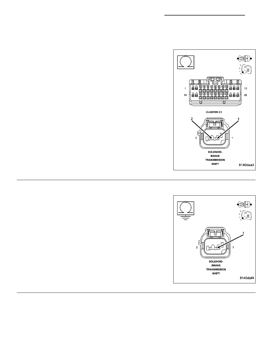
CHECK THE (B30) BTSI SOLENOID CONTROL CIRCUIT FOR A SHORT TO THE (Z101) BTSI SOLENOID
GROUND CIRCUIT.
Turn the ignition off.
Disconnect the BTSI solenoid harness connector.
Disconnect the Instrument Cluster C1 harness connector.
Measure the resistance between the (B30) BTSI Solenoid Control Cir-
cuit and the (Z101) BTSI Solenoid Ground Circuit.
Is the resistance below 5.0 ohms?
Yes
>> Repair the (B30) BTSI Solenoid Control circuit for a short
to the (Z101) BTSI Solenoid Ground Circuit.
Perform the BODY VERIFICATION TEST-VER 1. (Refer to
8 - ELECTRICAL/ELECTRONIC CONTROL MODULES/
FRONT CONTROL MODULE - DIAGNOSIS AND TEST-
ING)
No
>> Go To 3
3.
CHECK THE (B30) BTSI SOLENOID CONTROL CIRCUIT FOR A SHORT TO GROUND
Measure the resistance between ground and the (B30) BTSI Solenoid
Control circuit.
Is the resistance below 5.0 ohms?
Yes
>> Repair the (B30) BTSI Solenoid Control circuit for a short
to ground.
Perform the BODY VERIFICATION TEST-VER 1. (Refer to
8 - ELECTRICAL/ELECTRONIC CONTROL MODULES/
FRONT CONTROL MODULE - DIAGNOSIS AND TEST-
ING)
No
>> Go To 4
8J - 26
INSTRUMENT CLUSTER - ELECTRICAL DIAGNOSTICS
ND

P0930-BTSI CONTROL CIRCUIT LOW (CONTINUED)
4.
CHECK OPERATION OF THE BTSI SOLENOID
Reconnect the Instrument Cluster C1 harness connector.
Turn the ignition on.
Using a 12–volt test light connected to ground, check the BTSI Sole-
noid Control circuit.
With the scan tool, actuate the BTSI Solenoid.
Does the test light illuminate brightly?
Yes
>> Replace the Transmission Unlock (BTSI) Solenoid in
accordance with the Service Information.
Perform the BODY VERIFICATION TEST-VER 1. (Refer to
8 - ELECTRICAL/ELECTRONIC CONTROL MODULES/
FRONT CONTROL MODULE - DIAGNOSIS AND TEST-
ING)
No
>> Replace the Instrument Cluster in accordance with the
Service Information.
Perform the BODY VERIFICATION TEST-VER 1. (Refer to
8 - ELECTRICAL/ELECTRONIC CONTROL MODULES/
FRONT CONTROL MODULE - DIAGNOSIS AND TEST-
ING)
ND
INSTRUMENT CLUSTER - ELECTRICAL DIAGNOSTICS
8J - 27
P0931-BTSI CONTROL CIRCUIT HIGH
8J - 28
INSTRUMENT CLUSTER - ELECTRICAL DIAGNOSTICS
ND
P0931-BTSI CONTROL CIRCUIT HIGH (CONTINUED)
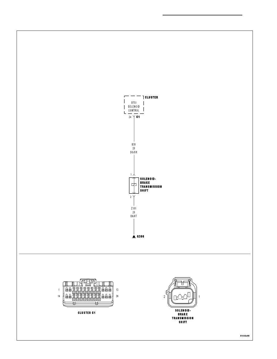
For the Instrument Cluster Solenoid circuit diagram (Refer to 8 - ELECTRICAL/INSTRUMENT CLUSTER - SCHE-
MATICS AND DIAGRAMS).
For a complete wiring diagram Refer to Section 8W.
•
When Monitored:
With the ignition in the Unlock or Run position and the driver’s foot applied to the brake pedal.
•
Set Condition:
The Instrument Cluster detects a high value on the BTSI Solenoid Control circuit.
Possible Causes
(Z101) BTSI SOLENOID GROUND CIRCUIT OPEN
(B30) BTSI SOLENOID CONTROL CIRCUIT OPEN
TRANSMISSION UNLOCK SOLENOID (BTSI)
INSTRUMENT CLUSTER
Diagnostic Test
1.
TEST FOR INTERMITTENT CONDITION
Turn the ignition on.
With the scan tool, record and erase DTCs.
Turn the ignition off, wait 10 seconds then turn the ignition on.
Apply and release the brakes.
With the scan tool, read DTCs.
Does the scan tool display: P0931-BTSI CONTROL CIRCUIT HIGH?
Yes
>> Go To 2
No
>> The condition that caused this code to set is not present at this time. Using the wiring diagram as a
guide, inspect the wiring and connectors for an intermittent condition. Operate the system several times
and recheck for active DTCs.
Perform the BODY VERIFICATION TEST-VER 1. (Refer to 8 - ELECTRICAL/ELECTRONIC CONTROL
MODULES/FRONT CONTROL MODULE - DIAGNOSIS AND TESTING)
2.
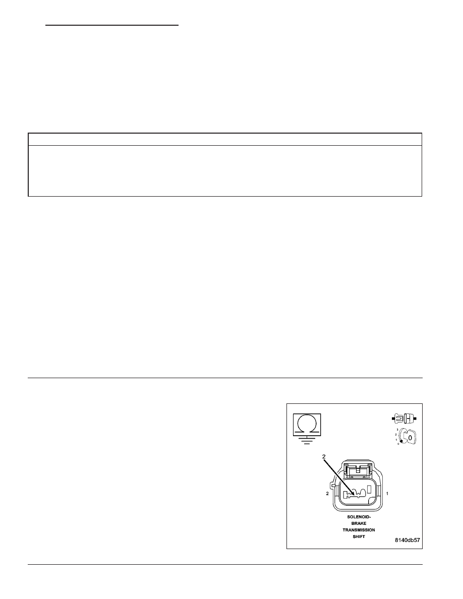
CHECK THE (Z101) BTSI SOLENOID GROUND CIRCUIT FOR AN OPEN
Turn the ignition off.
Disconnect the BTSI Solenoid harness connector.
Measure the resistance between ground and the (Z101) BTSI Solenoid
Ground circuit.
Is the resistance above 5.0 ohms?
Yes
>> Repair the (Z101) BTSI Solenoid Ground circuit for an
open.
Perform the BODY VERIFICATION TEST-VER 1. (Refer to
8 - ELECTRICAL/ELECTRONIC CONTROL MODULES/
FRONT CONTROL MODULE - DIAGNOSIS AND TEST-
ING)
No
>> Go To 3
ND
INSTRUMENT CLUSTER - ELECTRICAL DIAGNOSTICS
8J - 29
Нет комментариевНе стесняйтесь поделиться с нами вашим ценным мнением.
Текст