Dodge Dakota (ND). Manual — part 272
P0931-BTSI CONTROL CIRCUIT HIGH (CONTINUED)
3.
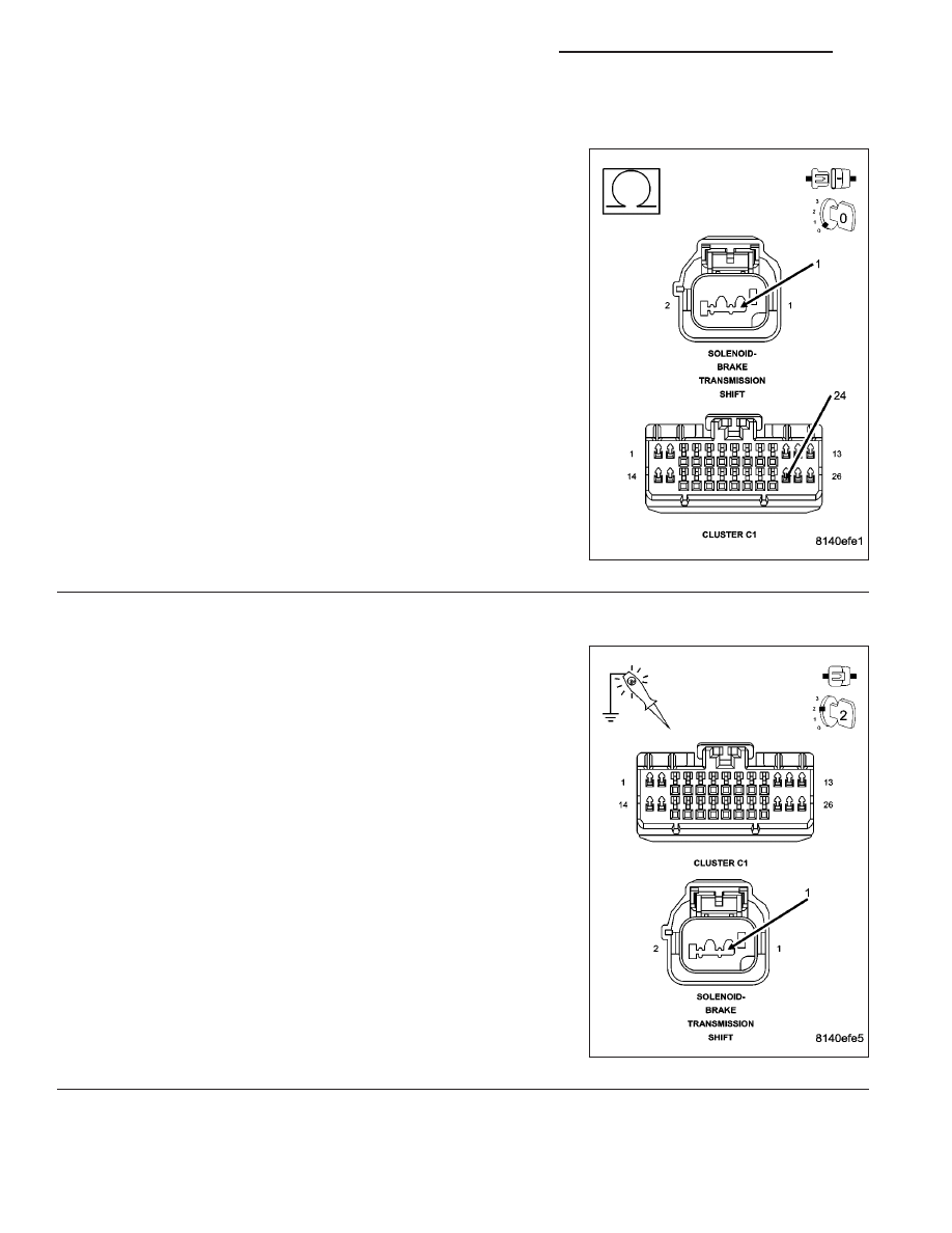
CHECK THE (B30) BTSI SOLENOID CONTROL CIRCUIT FOR AN OPEN
Disconnect the Instrument Cluster C1 harness connector.
Measure the resistance of the (B30) BTSI Solenoid Control circuit
between the BTSI Solenoid harness connector and the Instrument
Cluster C1 harness connector.
Is the resistance above 5.0 ohms?
Yes
>> Repair the (B30) BTSI Solenoid Control circuit for an
open.
Perform the BODY VERIFICATION TEST-VER 1. (Refer to
8 - ELECTRICAL/ELECTRONIC CONTROL MODULES/
FRONT CONTROL MODULE - DIAGNOSIS AND TEST-
ING)
No
>> Go To 4
4.
CHECK THE OPERATION OF THE BTSI SOLENOID
Reconnect the Instrument Cluster C1 harness connector.
Turn the ignition on.
Using a 12–volt test light connected to ground, check the (B30) BTSI
Solenoid Control circuit.
With the scan tool, actuate the BTSI Solenoid.
Does the test light illuminate brightly?
Yes
>> Replace the Transmission Unlock (BTSI)Solenoid in accor-
dance with the Service Information.
Perform the BODY VERIFICATION TEST-VER 1. (Refer to
8 - ELECTRICAL/ELECTRONIC CONTROL MODULES/
FRONT CONTROL MODULE - DIAGNOSIS AND TEST-
ING)
No
>> Replace the Instrument Cluster in accordance with the
Service Information.
Perform the BODY VERIFICATION TEST-VER 1. (Refer to
8 - ELECTRICAL/ELECTRONIC CONTROL MODULES/
FRONT CONTROL MODULE - DIAGNOSIS AND TEST-
ING)
8J - 30
INSTRUMENT CLUSTER - ELECTRICAL DIAGNOSTICS
ND
U0019–CAN B BUS
ND
INSTRUMENT CLUSTER - ELECTRICAL DIAGNOSTICS
8J - 31

U0019–CAN B BUS (CONTINUED)
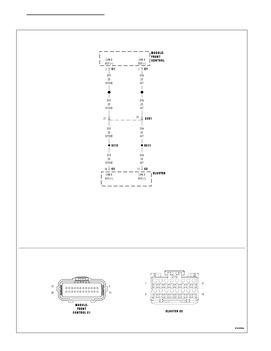
For a complete wiring diagram Refer to Section 8W.
•
When Monitored:
Continuously
•
Set Condition:
Whenever the Can B Bus (+) or B Bus (–) circuit is open, shorted to voltage or shorted to ground, this code
will set.
Possible Causes
CAN B BUS DTCs IN FRONT CONTROL MODULE
(D54) CAN B BUS (–) CIRCUIT OPEN
(D55) CAN B BUS (+) CIRCUIT OPEN
INSTRUMENT CLUSTER
Diagnostic Test
1.
TEST FOR INTERMITTENT CONDITION
Turn the ignition on.
With the scan tool, record and erase DTCs
Cycle the ignition from on to off 3 times.
Turn the ignition on.
With the scan tool, read DTCs.
Does the scan tool display U0019–CAN B BUS CIRCUIT?
Yes
>> Go To 2
No
>> The conditions that caused this code to set are not present at this time. Using the wiring diagram/sche-
matic as a guide, inspect the wiring and connectors.
Perform the BODY VERIFICATION TEST-VER 1. (Refer to 8 - ELECTRICAL/ELECTRONIC CONTROL
MODULES/FRONT CONTROL MODULE - DIAGNOSIS AND TESTING)
2.
CHECK FRONT CONTROL MODULE DTCs
With the scan tool, read Front Control Module DTCs
Does the scan tool display any CAN B BUS DTCs – ACTIVE?
Yes
>> Refer to the symptom list for problems related to Communication in the ELECTRICAL.– ELECTRONIC
CONTROL MODULES – ELECTRICAL DIAGNOSES section.
Perform the BODY VERIFICATION TEST-VER 1. (Refer to 8 - ELECTRICAL/ELECTRONIC CONTROL
MODULES/FRONT CONTROL MODULE - DIAGNOSIS AND TESTING)
No
>> Go to 3
8J - 32
INSTRUMENT CLUSTER - ELECTRICAL DIAGNOSTICS
ND
U0019–CAN B BUS (CONTINUED)
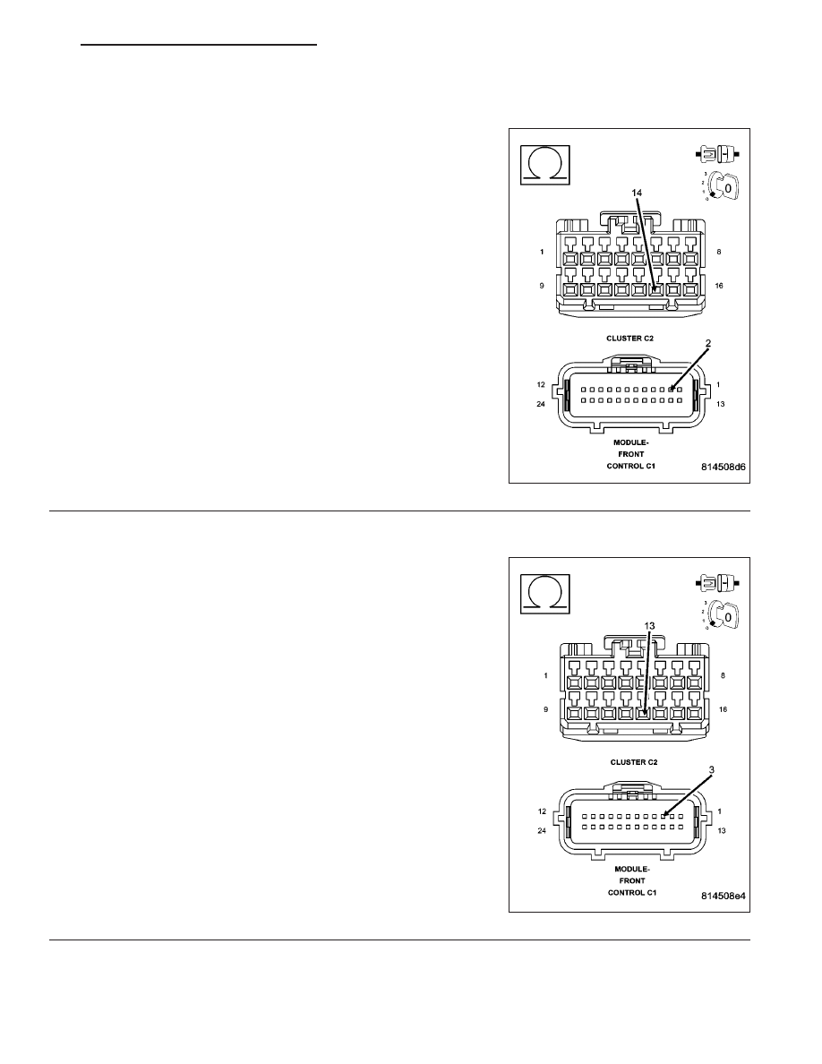
3.
CAN B BUS (+) CIRCUIT OPEN
Turn the ignition off.
Disconnect the Instrument Cluster C2 harness connector.
Disconnect the Front Control Module C1 harness connector.
Measure the resistance of the (D55) Can B Bus (+) circuit between the
Front Control Module C1 harness connector and the Instrument Clus-
ter C2 harness connector.
Is the resistance below 2.0 ohms?
Yes
>> Go To 4
No
>> Repair the Can B Bus (+) circuit for an open.
Perform the BODY VERIFICATION TEST-VER 1. (Refer to
8 - ELECTRICAL/ELECTRONIC CONTROL MODULES/
FRONT CONTROL MODULE - DIAGNOSIS AND TEST-
ING)
4.
CAN B BUS (–) CIRCUIT OPEN
Measure the resistance of the (D54) Can B Bus (–) circuit between the
Front Control Module C1 harness connector and the Instrument Clus-
ter C2 harness connector.
Is the resistance below 2.0 ohms?
Yes
>> Replace the Instrument Cluster in accordance with the ser-
vice information.
Perform the BODY VERIFICATION TEST-VER 1. (Refer to
8 - ELECTRICAL/ELECTRONIC CONTROL MODULES/
FRONT CONTROL MODULE - DIAGNOSIS AND TEST-
ING)
No
>> Repair the Can B Bus (–) circuit for an open.
Perform the BODY VERIFICATION TEST-VER 1. (Refer to
8 - ELECTRICAL/ELECTRONIC CONTROL MODULES/
FRONT CONTROL MODULE - DIAGNOSIS AND TEST-
ING)
ND
INSTRUMENT CLUSTER - ELECTRICAL DIAGNOSTICS
8J - 33
Нет комментариевНе стесняйтесь поделиться с нами вашим ценным мнением.
Текст