Dodge Dakota (ND). Manual — part 1065

P1790-FAULT IMMEDIATELY AFTER SHIFT
For the Transmission circuit diagram (Refer to 21 - TRANSMISSION/TRANSAXLE/AUTOMATIC - 45RFE/545RFE -
SCHEMATICS AND DIAGRAMS)
For a complete wiring diagram Refer to Section 8W
•
When Monitored:
After a speed ratio error is stored.
•
Set Condition:
This DTC is set if the associated speed ratio DTC is stored within 1.3 seconds after a shift.
Possible Causes
FAULT AFTER SHIFT
Always perform the Pre-Diagnostic Troubleshooting procedure before proceeding. (Refer to 21 - TRANSMIS-
SION/TRANSAXLE/AUTOMATIC - 45RFE/545RFE - DIAGNOSIS AND TESTING).
Theory of Operation
This DTC will only be stored along with a gear ratio DTC. If this DTC is set, it indicates a probable hydraulic (line
pressure) or mechanical problem exists. Diagnosing the transmission should be based on the associated speed
ratio DTC and mechanical causes should be considered first.
INTENDED GEAR
CLUTCHES APPLYING
RECOMENDED DTC
REVERSE
UD** - MS
P0738
1ST
UD - LR*
P0731
2ND
UD - 2C
P0732
2ND PRIME
UD - 4C
P1736
3RD
UD - OD/MS
P0733
4TH
OD/MS - 2C
P0734
5TH
OD/MS - 2C
P0735
* L/R is used only up to 150 output RPM in 1st gear. ** UD will show as applied in Reverse but the UD clutch is
actually released. OD/MS is OD and/or MS.
Diagnostic Test
1.
INTENDED GEAR TO APPLIED CLUTCH
With the scan tool, check the EATX DTC EVENT DATA to determine in which gear the slippage occurred and the
clutches that were applied.
With the EATX DTC EVENT DATA, use the information provided above to determine the proper symptom for diag-
nosis.
View repair
Repair
Refer to the Transmission category and perform the appropriate symptom identified from the EATX DTC
EVENT DATA, intended gear, and applied clutches.
Perform 45RFE/545RFE TRANSMISSION VERIFICATION TEST - VER 1.
21 - 652
AUTOMATIC TRANSMISSION 545RFE - ELECTRICAL DIAGNOSTICS
ND
P1794-SPEED SENSOR GROUND ERROR
ND
AUTOMATIC TRANSMISSION 545RFE - ELECTRICAL DIAGNOSTICS
21 - 653
P1794-SPEED SENSOR GROUND ERROR (CONTINUED)
For the Transmission circuit diagram (Refer to 21 - TRANSMISSION/TRANSAXLE/AUTOMATIC - 45RFE/545RFE -
SCHEMATICS AND DIAGRAMS)
For a complete wiring diagram Refer to Section 8W
•
When Monitored:
The gear ratio is monitored continuously while the Transmission is in gear.
•
Set Condition:
After a controller reset in neutral and a ratio of input to output, of 1 to 2. This DTC can take up to five minutes
of problem identification before illuminating the MIL.
Possible Causes
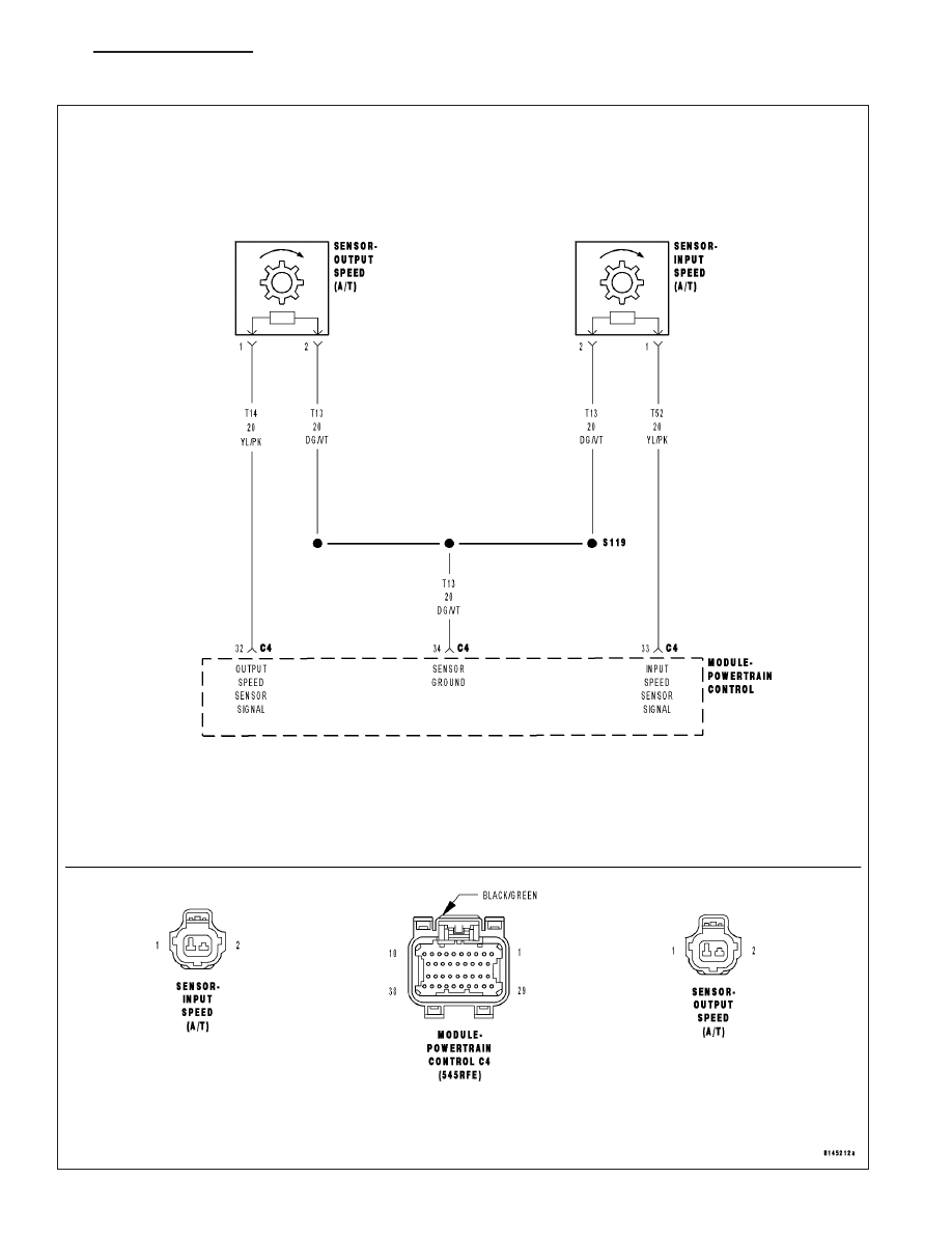
(T13) SPEED SENSOR GROUND CIRCUIT OPEN
(T13) SPEED SENSOR GROUND CIRCUIT SHORT TO GROUND
(T13) SPEED SENSOR GROUND CIRCUIT SHORT TO VOLTAGE
POWERTRAIN CONTROL MODULE
Always perform the Pre-Diagnostic Troubleshooting procedure before proceeding. (Refer to 21 - TRANSMIS-
SION/TRANSAXLE/AUTOMATIC - 45RFE/545RFE - DIAGNOSIS AND TESTING).
Theory of Operation
The transmission system uses two speed sensors, one to measure input RPM and one to measure output RPM.
These inputs are essential for proper transmission operation. Therefore, the integrity of this data is verified through
the following checks:
1) When in gear, if the gear ratio does not compare to a known gear ratio, the corresponding in-gear trouble code
is set (DTCs P0731–36).
2) An excessive change in input or output speeds indicating signal intermittent which may result in the DTCs P0715
and/or P0720 to set.
3) If the common speed sensor ground circuit is lost, both sensor inputs will read the signal from the input speed
sensor at idle in neutral. Since the input speed sensor reads 60 teeth from the input clutch hub and the output
speed sensor reads 30 teeth from the park gear, the result is an apparent speed ratio of 1:2 and may cause the
DTC P1794 to set when at a stop.
Diagnostic Test
1.
CHECK TO SEE IF DTC P1794 IS CURRENT
Engine Running, Shift lever in park.
With the scan tool, read the Transmission Output and Input Speed Sensor states.
Is the Output Speed Sensor reading twice the Input Speed Sensor reading?
Yes
>> Go To 2
No
>> Go To 6
21 - 654
AUTOMATIC TRANSMISSION 545RFE - ELECTRICAL DIAGNOSTICS
ND
P1794-SPEED SENSOR GROUND ERROR (CONTINUED)
2.
PCM AND WIRING
Turn the ignition off to the lock position.
Remove the Starter Relay.
NOTE: Removal of the Starter Relay is to prevent a Transmission, NO RESPONSE, condition and disable the
starter.
Install the Transmission Simulator, Miller tool 8333.
NOTE: Check connectors - Clean/repair as necessary.
With the Transmission Simulator, set the Input/Output Speed selector switch to the
9
3000/1000
9
position. Turn the
Input/Output Speed switch to
9
ON
9
.
Ignition on, engine not running.
With the scan tool, monitor the Input and Output Speed Sensor state.
Does the Input speed read 3000 RPM and the Output speed read 1000 RPM, within 50 RPM?
Yes
>> Go To 6
No
>> Go To 3
3.
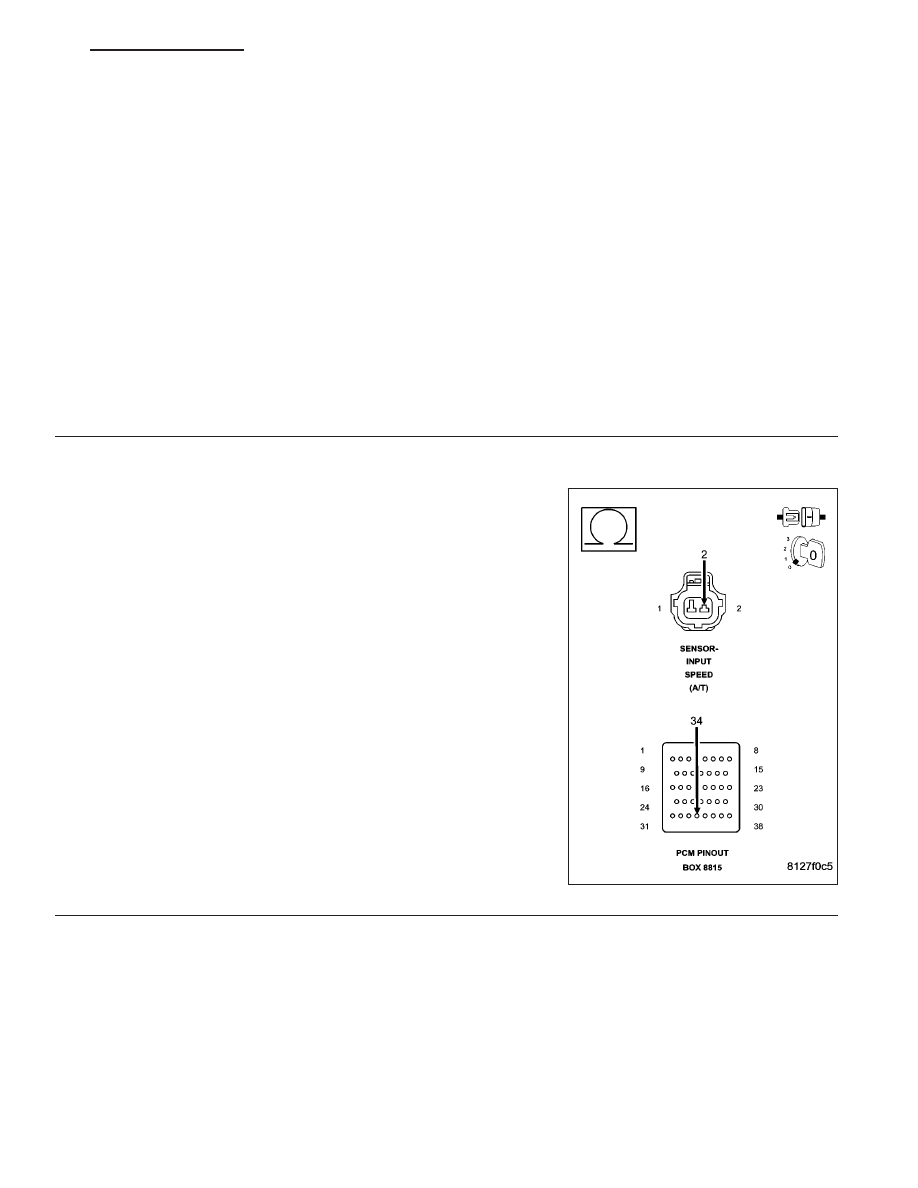
(T13) SPEED SENSOR GROUND CIRCUIT OPEN
Turn the ignition off to the lock position.
Disconnect the PCM C4 harness connector and connect Miller tool
#8815.
Disconnect the Transmission Simulator, Miller tool #8333.
CAUTION: Do not probe the PCM harness connectors. Probing
the PCM harness connectors will damage the PCM terminals
resulting in poor terminal to pin connection. Install Miller tool
#8815 to perform diagnosis.
Measure the resistance of the (T13) Speed Sensor Ground circuit from
the appropriate terminal of Miller tool #8815 to the Transmission Sole-
noid/TRS Assembly and both Input and Output Speed Sensor harness
connectors.
Is the resistance above 5.0 ohms on any of the above measure-
ments?
Yes
>> Repair the (T13) Speed Sensor Ground circuit for an
open.
Perform 45RFE/545RFE TRANSMISSION VERIFICATION
TEST - VER 1.
No
>> Go To 4
ND
AUTOMATIC TRANSMISSION 545RFE - ELECTRICAL DIAGNOSTICS
21 - 655
Нет комментариевНе стесняйтесь поделиться с нами вашим ценным мнением.
Текст