Dodge Dakota (ND). Manual — part 894
SPECIFICATIONS
TORQUE CHART
TORQUE SPECIFICATIONS
DESCRIPTION
N·m
Ft. Lbs.
In. Lbs.
Tilt Lever Release Knob
Bracket
Mounting Screws
4.5
—
40
Gear Shift Lever Assembly
Mounting Screws
12
—
105
Steering Column
Mounting Nuts
28
—
250
Steering Wheel
Bolt
61
45
—
Steering Coupler Shaft
Upper Pinch Bolt
38
28
—
Steering Coupler Shaft
Lower Pinch Bolt
38
28
—
Toe Plate
Nuts
12
—
105
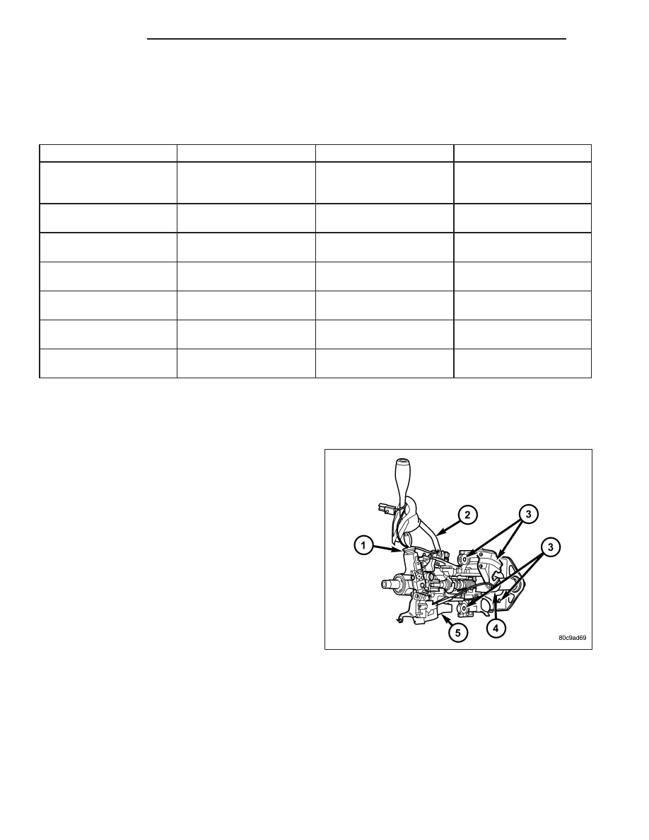
SWITCH-IGNITION
DESCRIPTION
The ignition switch (5) is located on the steering col-
umn (4). It is used as the main on/off switching device
for most electrical components. The mechanical key
cylinder is used to engage/disengage the electrical
ignition switch.
OPERATION
Vehicles equipped with an automatic transmission and a steering column mounted shifter: an interlock
device is located within the shift cable. This interlock device is used to lock the transmission shifter in the PARK
position when the key cylinder is in any position and the brake pedal is not depressed.
19 - 16
COLUMN
ND

DIAGNOSIS AND TESTING
IGNITION SWITCH
TEST AND REPAIR
If the key removal effort is excessive on a vehicle with a automatic transmission first adjust the shift linkage, (Refer
to 21 - TRANSMISSION/TRANSAXLE/AUTOMATIC - 46RE/GEAR SHIFT CABLE - ADJUSTMENTS).
If the ignition switch effort is excessive remove the ignition key cylinder from the steering column. (Refer to 19 -
STEERING/COLUMN/LOCK CYLINDER HOUSING - REMOVAL). Check the turning effort of the key cylinder. If the
ignition key cylinder effort is excessive replace the key cylinder. If the ignition key cylinder operates properly look for
the following conditions.
REMOVAL
SERVICE PRECAUTIONS
NOTE: The steering column on vehicles equipped
with an automatic transmission is not equipped
with an internal locking shaft with the ignition cyl-
inder. Alternative methods of locking the steering
wheel for service will have to be used.
The tilt and standard column (4) have been designed
to be serviced as an assembly; without wiring,
switches, shrouds, steering wheel, etc. Most steering
column components can be serviced without removing
the steering column from the vehicle.
Safety goggles should be worn at all times when
working on steering columns.
To service the steering wheel, switches or airbag,
Refer to Electrical Restraints and follow all WARN-
INGS and CAUTIONS.
WARNING: THE AIRBAG SYSTEM IS A SENSITIVE, COMPLEX ELECTRO-MECHANICAL UNIT. BEFORE
ATTEMPTING TO DIAGNOSE, REMOVE OR INSTALL THE AIRBAG SYSTEM COMPONENTS YOU MUST
FIRST DISCONNECT AND ISOLATE THE BATTERY NEGATIVE (GROUND) CABLE. THEN WAIT TWO MIN-
UTES FOR THE SYSTEM CAPACITOR TO DISCHARGE. FAILURE TO DO SO COULD RESULT IN ACCIDEN-
TAL DEPLOYMENT OF THE AIRBAG AND POSSIBLE PERSONAL INJURY. THE FASTENERS, SCREWS, AND
BOLTS, ORIGINALLY USED FOR THE AIRBAG COMPONENTS, HAVE SPECIAL COATINGS AND ARE SPE-
CIFICALLY DESIGNED FOR THE AIRBAG SYSTEM. THEY MUST NEVER BE REPLACED WITH ANY SUBSTI-
TUTES. ANYTIME A NEW FASTENER IS NEEDED, REPLACE WITH THE CORRECT FASTENERS PROVIDED
IN THE SERVICE PACKAGE OR FASTENERS LISTED IN THE PARTS BOOKS.
CAUTION: Do not hammer on steering column shaft. This may cause damage to the shaft or bearing.
CAUTION: Do not attempt to remove the pivot bolts to disassemble the tilting mechanism.
The ignition key must be in the key cylinder for cylinder removal. The key cylinder must be removed first before
removing ignition switch.
1. Remove the negative (ground) cable from the battery.
2. Disable the airbag, (Refer to 8 - ELECTRICAL/RESTRAINTS/DRIVER AIRBAG - REMOVAL).
3. Remove the lower and upper shrouds.
4. Remove key cylinder. (Refer to 19 - STEERING/COLUMN/LOCK CYLINDER HOUSING - REMOVAL).
5. Disconnect the lower clockspring connectors.
6. Remove the wire retainer from the tilt lever bracket.
ND
COLUMN
19 - 17
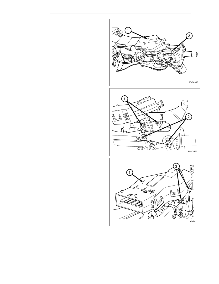
7. Remove the tilt lever mounting screws to gain
access to the ignition switch (1) mounting screws.
8. For columns without tilt remove the bracket (2) to
gain access to the ignition switch mounting screws
(2).
9. Disconnect the electrical connector at rear of igni-
tion switch (1).
10. Remove ignition switch mounting screw (2).
11. Using a small screwdriver, push on locking tab
and remove switch from steering column.
INSTALLATION
The ignition key must be in the key cylinder for cylinder removal. The key cylinder must be removed first before
installing ignition switch.
1. Before installing ignition switch, rotate the slot in the switch to the ON position.
19 - 18
COLUMN
ND
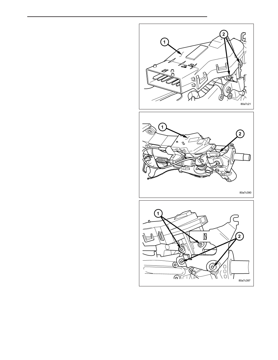
2. Connect the electrical connector to rear of the igni-
tion switch. Make sure that locking tabs are fully
seated into wiring connector.
3. Position switch (1) to column and install the mount-
ing screw (2). Tighten screw to 3 N·m (26 in. lbs.).
4. Install the tilt lever bracket (2) mounting screws.
Tighten screws to 4.5 N·m (40 in. lbs.).
5. If the column is non-tilt install the bracket (2).
Tighten screws to 4.5 N·m (40 in. lbs.)
ND
COLUMN
19 - 19
Нет комментариевНе стесняйтесь поделиться с нами вашим ценным мнением.
Текст