Dodge Dakota (ND). Manual — part 872
3. Install the fascia support bracket. (Refer to 13 - FRAME & BUMPERS/BUMPERS/BRACKET-FASCIA SUPPORT
- INSTALLATION)
4. Check front fascia gap and flush positioning. (Refer to 23 - BODY/BODY STRUCTURE/GAP AND FLUSH -
SPECIFICATIONS)
5. loosen the nuts (1 and 3) and adjust the front fascia to specifications.
6. Tighten the nuts to 94 N·m (70 ft. lbs.).
FRAME
WARNING
SAFETY PRECAUTIONS AND WARNINGS
WARNING: BEFORE PERFORMING ANY WELDING OPERATIONS DISCONNECT AND ISOLATE THE BAT-
TERY NEGATIVE (GROUND) CABLE AND DISCONNECT ALL WIRE HARNESS CONNECTORS FROM THE
AIRBAG CONTROL MODULE (ACM). FAILURE TO TAKE THE PROPER PRECAUTIONS COULD RESULT IN
ACCIDENTAL AIRBAG
DEPLOYMENT AND
OTHER
POSSIBLE
DAMAGE
TO
THE
SUPPLEMENTAL
RESTRAINT SYSTEM CIRCUITS AND COMPONENTS.
•
USE EYE PROTECTION WHEN GRINDING OR WELDING METAL, SERIOUS EYE INJURY CAN RESULT.
•
BEFORE PROCEEDING WITH FRAME REPAIR INVOLVING GRINDING OR WELDING, VERIFY THAT VEHI-
CLE FUEL SYSTEM IS NOT LEAKING OR IN CONTACT WITH REPAIR AREA, PERSONAL INJURY CAN
RESULT.
•
DO NOT ALLOW OPEN FLAME OR HEAT AND METAL SPATTER FROM ARC WELDING, TO CONTACT
PLASTIC BODY PANELS. FIRE OR EXPLOSION CAN RESULT.
•
WHEN WELDED FRAME COMPONENTS ARE REPLACED, ENSURE COMPLETE PENETRATION WELD IS
ACHIEVED DURING INSTALLATION. IF NOT, DANGEROUS OPERATING CONDITIONS CAN RESULT.
•
STAND CLEAR OF CABLES OR CHAINS ON PULLING EQUIPMENT DURING FRAME STRAIGHTENING
OPERATIONS, PERSONAL INJURY CAN RESULT.
•
DO NOT VENTURE UNDER A HOISTED VEHICLE THAT IS NOT SUPPORTED ON SAFETY STANDS, PER-
SONAL INJURY CAN RESULT.
•
NO HEAT MAY BE USED IF FRAME STRAIGHTENING IS REQUIRED. THE USE OF HEAT IS ACCEPTABLE
IN THOSE SITUATIONS WHERE THE PART BEING HEATED WILL BE REPLACED. FAILURE TO FOLLOW
THESE INSTRUCTIONS MAY RESULT IN PERSONAL INJURY.
CAUTION: Do not reuse damaged fasteners, quality of repair would be suspect. Failure to use only produc-
tion fasteners or fasteners of equivalent hardness can result in loosening or failure. Do not drill any holes
in the frame that are not specifically outlined in this or other, DaimlerChrysler procedure as frame rail failure
can result.
13 - 8
FRAME & BUMPERS
ND

SPECIFICATIONS
WELD PROCESS
CAUTION: All welds should conform to DaimlerChrysler vehicle engineering process standard “ps 9472”.
WELDING PARAMETERS
WELDING PROCESS
FLUX CORED ARC
GAS METAL ARC
(MIG)*
SHIELDED METAL ARC
(STICK)
Material Thickness
3.7 mm to 4.2 mm
3.7 mm to 4.2 mm
3.7 mm to 4.2 mm
Electrode Type
Lincoln Electrical Co.
Product #: NR-211 MP
(Do Not Substitute)
AWS ER70S-3
(Do Not Substitute)
** AWS E 7018
Electrodes Size Inches
.045 Tubular
.035 Solid
3/32
9
Electrode Stick Out
3/8
9
- 1/2
9
1/2
9
- 5/8
9
N/A
Polarity
Electrode
9
-
9
Work Piece
9
+
9
Electrode
9
+
9
Work Piece
9
-
9
Electrode
9
+
9
Work Piece
9
-
9
Shielding Gas
Self Shielded
75% Ar
25% CO2
Self Shielded
Gas Flow Rate
N/A
25 - 35 CFM
N/A
Wire Feed Speed
(inches per minute)
110 - 130 Vertical Down
70 - 90 Flat & Overhead
245 - 250 Vertical Down
210 - 225 Flat &
Overhead
N/A
Approximate Amperage
Vertical
110 - 130
175
85 (3/32
9
Diameter)
Flat & Overhead
70 - 90
155
90 (3/32
9
Diameter)
Voltage
15 - 18
19 - 20
N/A
Direction of Welding
Vertical
Vertical Down Hill (only)
Vertical Down Hill (only)
Vertical - Up Hill (only)
Flat & Overhead
Flat - Push or Drag
Flat - Push or Drag
Flat - Drag
*First choice - Gas Metal Arc Welding Process: Butt joints - apply two layers (passes) of weld metal. First pass
should only fill approximately
1
⁄
2
the thickness. Vertical position welds - maintain electrode wire at leading edge of
weld puddle while traveling down hill to produce maximum penetration into the sleeve. These techniques work for
FCAW as well.
**E7018 new electrodes may be exposed to the atmosphere for up to ten hours with no harmful effect.
Reconditioning schedules should come from the manufacturer.
FRAME DIMENSIONS
Frame dimensions are listed in metric scale. All dimensions are from center to center of Principal Locating Point
(PLP), or from center to center of PLP and fastener location.
ND
FRAME & BUMPERS
13 - 9

VEHICLE PREPARATION
Position the vehicle on a frame alignment rack, refer to instructions provided with equipment being used. Adjust the
vehicle PLP heights to the specified dimension above the work surface (datum line). Vertical dimensions can be
taken from the datum line to the locations indicated were applicable.
DESCRIPTION
FIGURE
ND 33 TOP VIEW - (4 X 2)
1
ND 33 LEFT SIDE VIEW - (4 X 2)
2
ND 33 TOP VIEW - (4 X 4)
3
ND 33 LEFT SIDE VIEW - (4 X 4)
4
ND 84 TOP VIEW - (4 X 2)
5
ND 84 LEFT SIDE VIEW - (4 X 2)
6
ND 84 TOP VIEW - (4 X 4)
7
ND 84 LEFT SIDE VIEW - (4 X 4)
8
13 - 10
FRAME & BUMPERS
ND
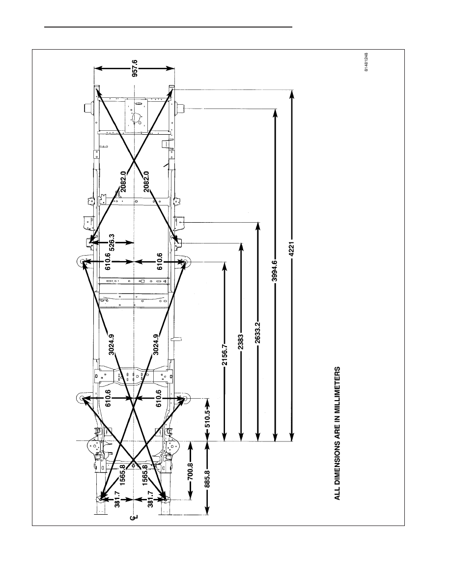
F
ig
.1N
D3
3T
O
P
V
IE
W-(
4X2
)
ND
FRAME & BUMPERS
13 - 11
Нет комментариевНе стесняйтесь поделиться с нами вашим ценным мнением.
Текст