Dodge Dakota (ND). Manual — part 1104
REMOVAL
1. Remove transmission and torque converter from vehicle. (Refer to 21 - TRANSMISSION/AUTOMATIC - 545RFE/
42RLE - REMOVAL)
2. Place a suitable drain pan under the converter housing end of the transmission.
CAUTION: Verify that transmission is secure on the lifting device or work surface, the center of gravity of
the transmission will shift when the torque converter is removed creating an unstable condition. The torque
converter is a heavy unit. Use caution when separating the torque converter from the transmission.
3. Pull the torque converter forward until the center hub clears the oil pump seal.
4. Separate the torque converter from the transmission.
INSTALLATION
NOTE: Check converter hub and drive flats for sharp edges, burrs, scratches, or nicks. Polish the hub and
flats with 320/400 grit paper or crocus cloth if necessary. Verify that the converter hub o-ring is properly
installed and is free from debris. The hub must be smooth to avoid damaging the pump seal at installation.
1. Lubricate oil pump seal lip with transmission fluid.
2. Place torque converter in position on transmission.
CAUTION: Do not damage oil pump seal or con-
verter hub o-ring while inserting torque converter
into the front of the transmission.
3. Align torque converter to oil pump seal opening.
4. Insert torque converter hub into oil pump.
5. While pushing torque converter inward, rotate con-
verter until converter is fully seated in the oil pump
gears.
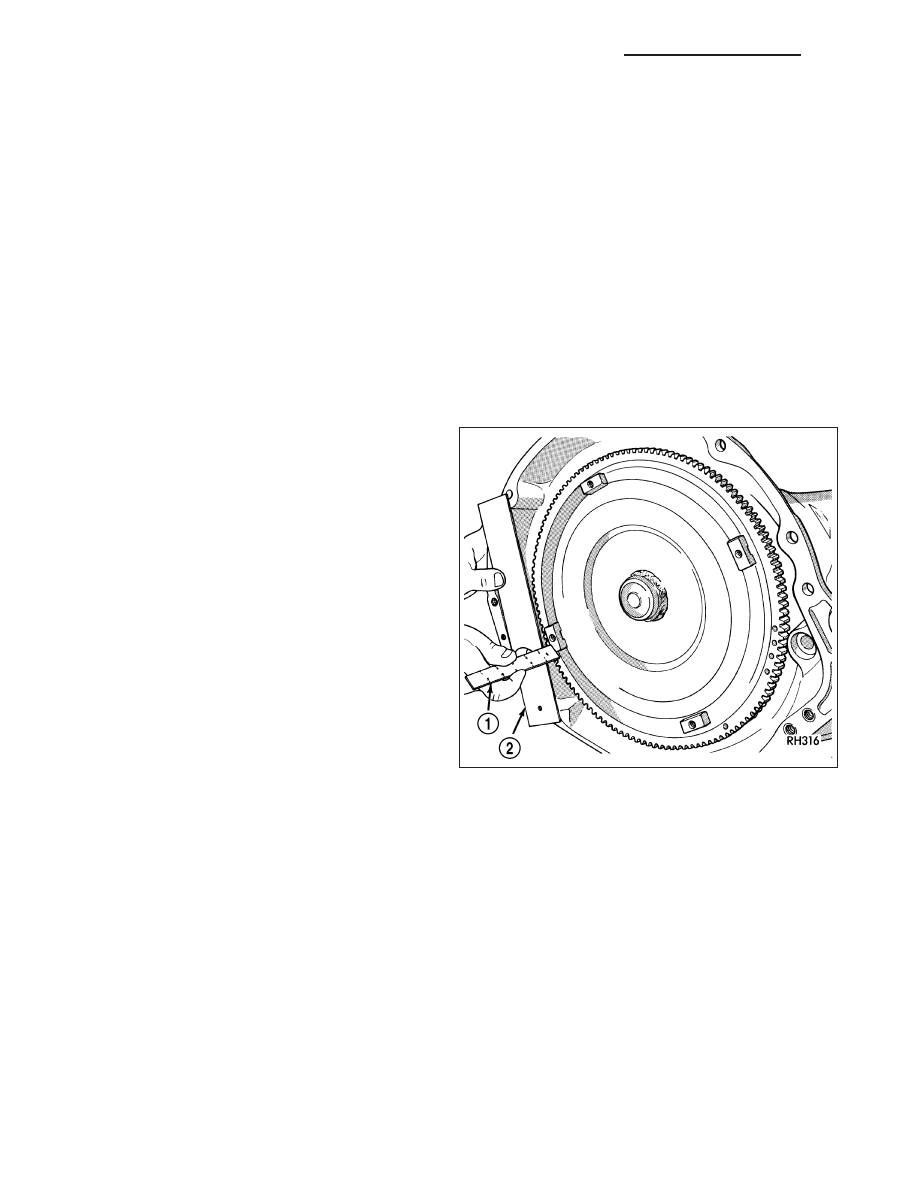
6. Check converter seating with a scale (1) and
straightedge (2). Surface of converter lugs should
be at least 13 mm (1/2 in.) to rear of straightedge
when converter is fully seated.
7. If necessary, temporarily secure converter with
C-clamp attached to the converter housing.
8. Install the transmission in the vehicle.
9. Fill the transmission with the recommended fluid.
21 - 808
AUTOMATIC TRANSMISSION 545RFE - SERVICE INFORMATION
ND

SWITCH-TOW/HAUL OVERDRIVE
DESCRIPTION
The tow/haul overdrive OFF (control) switch is located
in the shift lever arm. The switch is a momentary con-
tact device that signals the PCM to toggle current sta-
tus of the overdrive function.
OPERATION
At key-on, overdrive operation is allowed. Pressing the switch once causes the tow/haul overdrive OFF mode to be
entered and the Tow/Haul lamp to be illuminated. Pressing the switch a second time causes normal overdrive oper-
ation to be restored and the tow/haul lamp to be turned off. The tow/haul overdrive OFF mode defaults to ON after
the ignition switch is cycled OFF and ON. The normal position for the control switch is the ON position. The switch
must be in this position to energize the solenoid and allow a 3-4 upshift. The control switch indicator light illuminates
only when the tow/haul overdrive switch is turned to the OFF position, or when illuminated by the transmission
control module.
REMOVAL
1. Using a plastic trim tool, remove the tow/haul over-
drive off switch retainer (2) from the shift lever (1).
ND
AUTOMATIC TRANSMISSION 545RFE - SERVICE INFORMATION
21 - 809
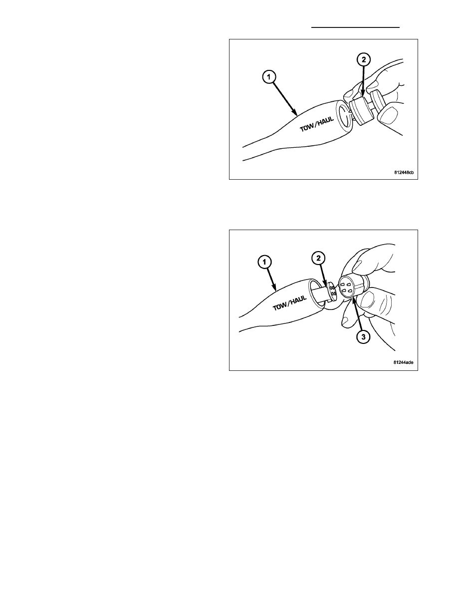
2. Pull the switch (2) outwards to release it from the
connector in the lever (1)
INSTALLATION
NOTE: There is enough slack in the wire to pull out the connector from the lever.
1. Pull the connector (2) out of the lever (1) just
enough to grasp it.
CAUTION: Be careful not to bend the pins on the
tow/haul overdrive off switch. Use care when
installing the switch, as it is not indexed, and can
be accidentally installed incorrectly.
2. Install the tow/haul overdrive off switch (3) into the
connector (2)
3. Push the tow/haul overdrive off switch (3) and wir-
ing into the shift lever (1).
4. Install the tow/haul overdrive off switch retainer
onto the shift lever.
RELAY-TRANSMISSION CONTROL
DESCRIPTION
The relay is supplied fused B+ voltage, energized by the TCM, and is used to supply power to the solenoid pack
when the transmission is in normal operating mode.
OPERATION
When the relay is “off”, no power is supplied to the solenoid pack and the transmission is in “limp-in” mode. After a
controller reset, the TCM energizes the relay. Prior to this, the TCM verifies that the contacts are open by checking
for no voltage at the switched battery terminals. After this is verified, the voltage at the solenoid pack pressure
switches is checked. After the relay is energized, the TCM monitors the terminals to verify that the voltage is greater
than 3 volts.
21 - 810
AUTOMATIC TRANSMISSION 545RFE - SERVICE INFORMATION
ND
SENSOR-TRANSMISSION RANGE
DESCRIPTION
The Transmission Range Sensor (TRS) is part of the solenoid module, which is mounted to the top of the valve
body inside the transmission.
The Transmission Range Sensor (TRS) has five switch contact pins that:
•
Determine shift lever position
•
Supply ground to the Starter Relay in Park and Neutral only.
•
Supply +12 V to the backup lamps in Reverse only.
The TRS also has an integrated temperature sensor (thermistor) that communicates transmission temperature to the
TCM and PCM.
OPERATION
The Transmission Range Sensor (TRS) communicates shift lever position to the TCM as a combination of open and
closed switches. Each shift lever position has an assigned combination of switch states (open/closed) that the TCM
receives from four sense circuits. The TCM interprets this information and determines the appropriate transmission
gear position and shift schedule.
There are many possible combinations of open and closed switches (codes). Seven of these possible codes are
related to gear position and five are recognized as “between gear” codes. This results in many codes which should
never occur. These are called “invalid” codes. An invalid code will result in a DTC, and the TCM will then determine
the shift lever position based on pressure switch data. This allows reasonably normal transmission operation with a
TRS failure.
GEAR
C5
C4
C3
C2
C1
Park
CL
OP
OP
CL
CL
Temp 1
CL
OP
OP
CL
OP
Reverse
OP
OP
OP
CL
OP
Temp 2
OP
OP
CL
CL
OP
Neutral 1
OP
OP
CL
CL
CL
Neutral 2
OP
CL
CL
CL
CL
Temp 3
OP
CL
CL
CL
OP
Drive
OP
CL
CL
OP
OP
Temp 4
OP
CL
OP
OP
OP
Manual 2
CL
CL
OP
OP
OP
Temp 5
CL
OP
OP
OP
OP
Manual 1
CL
OP
CL
OP
OP
ND
AUTOMATIC TRANSMISSION 545RFE - SERVICE INFORMATION
21 - 811
Нет комментариевНе стесняйтесь поделиться с нами вашим ценным мнением.
Текст