Dodge Dakota (ND). Manual — part 341
*DRIVER DOOR UNLOCK OUTPUT CIRCUIT SHORTED TO GROUND (CONTINUED)
2.
CHECK (P1) DOOR UNLOCK DRIVER LEFT FRONT FOR SHORT TO GROUND
NOTE: If only one motor is inoperative when the door locks are actuated, disconnect that motor and retest
to see if the DTC is still present. If it is not, replace the defective motor.
Turn the ignition off.
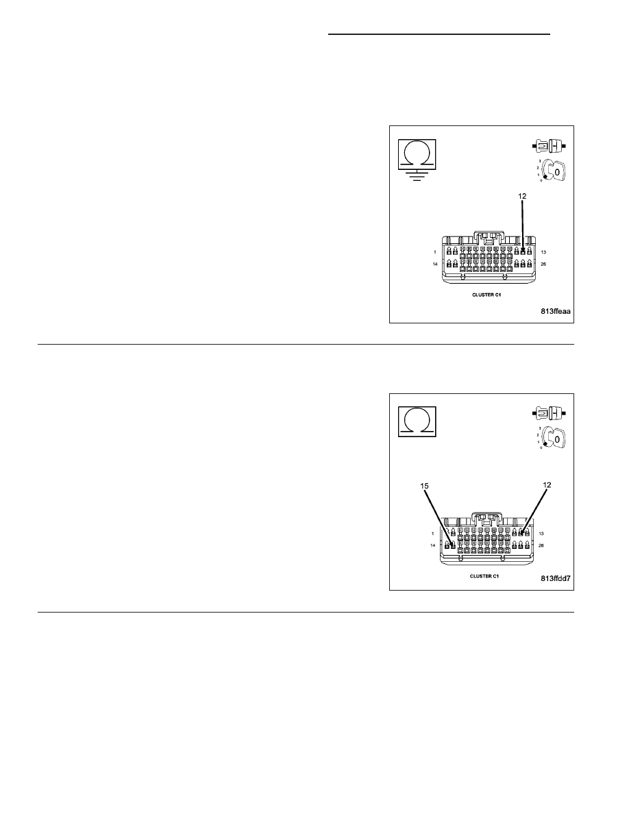
Disconnect the Cluster C1 connector.
Measure the resistance between ground and the (P1) Door Unlock
Driver Left Front circuit.
Is the resistance below 1000.0 ohms?
No
>> Go To 3
Yes
>> Repair the (P1) Door Unlock Driver Left Front circuit for a
short to ground.
Perform BODY VERIFICATION TEST - VER 1. (Refer to 8
- ELECTRICAL/POWER LOCKS - DIAGNOSIS AND
TESTING)
3.
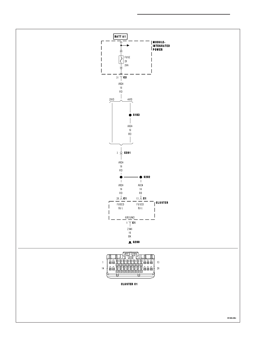
CHECK THE (P1) DOOR UNLOCK DRIVER LEFT FRONT FOR A SHORT TO THE (P393) DOOR LOCK
DRIVER LEFT DOORS
Measure the resistance between the (P1) Door Unlock Driver Left
Front and the (P393) Door Lock Driver Left Doors circuits.
Is the resistance below 2.0 ohms?
No
>> Go To 4
Yes
>> Repair the (P1) Door Unlock Driver Left Front circuit for a
short to the (P393) Door Lock Driver Left Doors circuit.
Perform BODY VERIFICATION TEST - VER 1. (Refer to 8
- ELECTRICAL/POWER LOCKS - DIAGNOSIS AND
TESTING)
8N - 40
POWER LOCKS - ELECTRICAL DIAGNOSTICS
ND

*DRIVER DOOR UNLOCK OUTPUT CIRCUIT SHORTED TO GROUND (CONTINUED)
4.
CHECK THE (P1) DOOR UNLOCK DRIVER LEFT FRONT CIRCUIT FOR A SHORT TO THE (P5) DOOR
UNLOCK DRIVER LEFT REAR CIRCUIT
Measure the resistance between the (P1) Door Unlock Driver Left
Front circuit and the (P5) Door Unlock Driver Left Rear circuit.
Is the resistance below 3.0 ohms?
No
>> Replace the Instrument Cluster in accordance with service
information.Perform BODY VERIFICATION TEST - VER 1.
(Refer to 8 - ELECTRICAL/POWER LOCKS - DIAGNOSIS
AND TESTING)
Yes
>> Repair the (P1) Door Unlock Driver Left Front circuit for a
short to the (P5) Door Unlock Driver Left Rear circuit.
Perform BODY VERIFICATION TEST - VER 1. (Refer to 8
- ELECTRICAL/POWER LOCKS - DIAGNOSIS AND
TESTING)
ND
POWER LOCKS - ELECTRICAL DIAGNOSTICS
8N - 41
*ALL DOOR LOCKS INOPERATIVE
8N - 42
POWER LOCKS - ELECTRICAL DIAGNOSTICS
ND

*ALL DOOR LOCKS INOPERATIVE (CONTINUED)
For the Power Door Locks circuit diagram (Refer to 8 - ELECTRICAL/POWER LOCKS - SCHEMATICS AND DIA-
GRAMS).
For a complete wiring diagram Refer to Section 8W.
Possible Causes
DTC PRESENT
FUSE #20 OPEN
(A924) FUSE B+ CIRCUIT OPEN
(Z946) GROUND CIRCUIT OPEN
INSTRUMENT CLUSTER
Diagnostic Test
1.
DTC PRESENT
Turn the ignition on.
With the scan tool , read DTC’s.
Does the scan tool display any Door Lock or Cluster related
DTC’s?
Yes
>> Refer to the Table of Contents in this section and repair
the DTC’s.
No
>> Go To 2
2.
FUSE #20 OPEN
With the fuse installed, test both sides of fuse #20 in the IPM.
Is there 12 volts on both sides of the fuse?
Yes
>> Go To 3
No
>> Replace the fuse if open and retry the system. If the fuse
blows, locate and repair a short to the Instrument Cluster.
The 12 volt supply to the fuse is a bus bar in the IPM.
Perform BODY VERIFICATION TEST - VER 1. (Refer to 8
- ELECTRICAL/POWER LOCKS - DIAGNOSIS AND
TESTING)
ND
POWER LOCKS - ELECTRICAL DIAGNOSTICS
8N - 43
Нет комментариевНе стесняйтесь поделиться с нами вашим ценным мнением.
Текст