Dodge Dakota (ND). Manual — part 133
LEAKS
Viscous fan drive operation is not affected by small oil stains near the drive bearing. If leakage appears excessive,
replace the fan drive unit.
VISCOUS DRIVE
If the fan assembly free-wheels without drag (the fan blades will revolve more than five turns when spun by hand),
replace the fan drive. This spin test must be performed when the engine is cool.
For the following test, the cooling system must be in good condition. It also will ensure against excessively high
coolant temperature.
WARNING: BE SURE THAT THERE IS ADEQUATE FAN BLADE CLEARANCE BEFORE DRILLING.
1. Drill a 3.18-mm (1/8-in) diameter hole in the top center of the fan shroud.
2. Obtain a dial thermometer with an 8 inch stem (or equivalent). It should have a range of -18°-to-105°C (0°-to-
220° F). Insert thermometer through the hole in the shroud. Be sure that there is adequate clearance from the
fan blades.
3. Connect a tachometer and an engine ignition timing light. The timing light is to be used as a strobe light. This
step cannot be used on the diesel engine.
4. Block the air flow through the radiator. Secure a sheet of plastic in front of the radiator. Use tape at the top to
secure the plastic and be sure that the air flow is blocked.
5. Be sure that the air conditioner (if equipped) and blowe fan is turned off.
WARNING: USE EXTREME CAUTION WHEN THE ENGINE IS OPERATING. DO NOT STAND IN A DIRECT LINE
WITH THE FAN. DO NOT PUT YOUR HANDS NEAR THE PULLEYS, BELTS OR FAN. DO NOT WEAR LOOSE
CLOTHING.
6. Start the engine and operate at 2400 rpm. Within ten minutes the air temperature (indicated on the dial ther-
mometer) should be up to 88° C (190° F). Fan drive engagement should start to occur at/between:
•
3.7L Automatic - 93° C - 99°C (200° F - 210° F)
•
3.7L Manual/4.7L Automatic/5.9L - 85° - 91° C (185° - 195° F)
•
4.7L Manual - 74° - 79° C (165° - 175° F)
•
5.7L
•
5.9L
•
Engagement is distinguishable by a definite increase in fan flow noise (roaring). The timing light also will
indicate an increase in the speed of the fan.
7. When viscous drive engagement is verified, remove the plastic sheet. Fan drive disengagement should start to
occur at or between:
•
3.7L Automatic - 76°C - 81°C (168° F - 178° F)
•
3.7L Manual/4.7L Auto/ 5.9L - 67°C - 73°C (153° F - 163° F)
•
4.7L Manual - 56°C - 62°C (133° F - 143° F)
•
5.7L A definite decrease of fan flow noise (roaring) should be noticed. If not, replace the defective viscous fan
drive unit.
CAUTION: Some engines equipped with serpentine drive belts have reverse rotating fans and viscous fan
drives. They are marked with the word REVERSE to designate their usage. Installation of the wrong fan or
viscous fan drive can result in engine overheating.
7 - 44
ENGINE
ND
CAUTION: If the viscous fan drive is replaced because of mechanical damage, the cooling fan blades
should also be inspected. Inspect for fatigue cracks, loose blades, or loose rivets that could have resulted
from excessive vibration. Replace fan blade assembly if any of these conditions are found. Also inspect
water pump bearing and shaft assembly for any related damage due to a viscous fan drive malfunction.
REMOVAL
1. Partially drain the cooling system (Refer to 7 - COOLING - STANDARD PROCEDURE).
2. Remove the upper radiator hose.
3. Remove the air filter housing assembly (Refer to 9 - ENGINE/AIR INTAKE SYSTEM/AIR CLEANER ELEMENT
- REMOVAL).
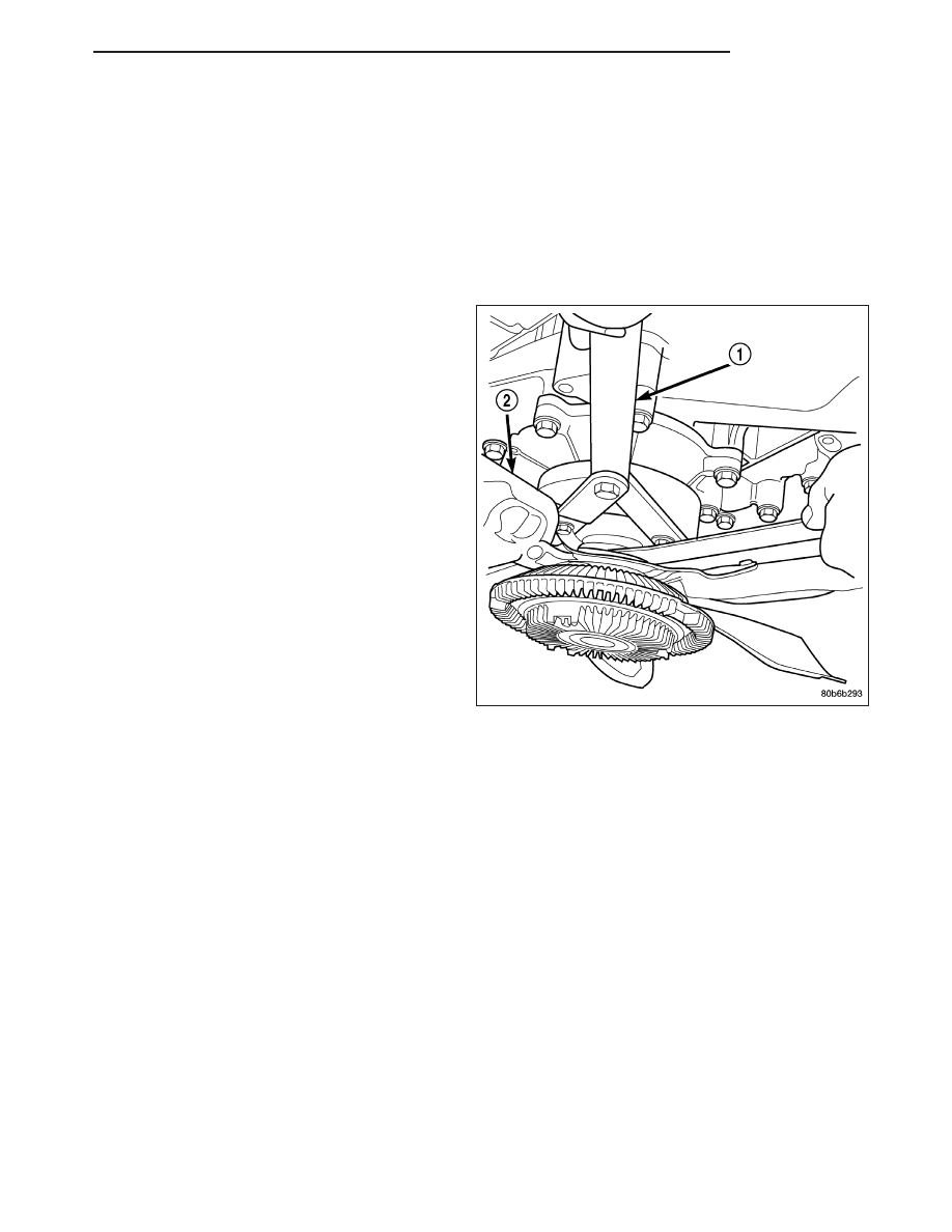
4. Using Tool 6958 and adapter pins 8346 (1), remove
fan/viscous fan drive assembly from water pump.
Do not attempt to remove fan/viscous fan drive
assembly from vehicle at this time.
5. Position the fan/fan drive assembly in the radiator
shroud.
6. Remove the two shroud mounting screws.
7. Remove the radiator shroud and fan drive assembly.
8. After removing fan blade/viscous fan drive assembly, do not place viscous fan drive in horizontal position. If
stored horizontally, silicone fluid in the viscous fan drive could drain into its bearing assembly and contaminate
lubricant.
9. Remove four bolts securing fan blade assembly to viscous fan drive.
CLEANING
Clean the fan blades using a mild soap and water. Do not use an abrasive to clean the blades.
INSPECTION
WARNING: DO NOT ATTEMPT TO BEND OR STRAIGHTEN FAN BLADES IF FAN IS NOT WITHIN SPECIFI-
CATIONS.
CAUTION: If fan blade assembly is replaced because of mechanical damage, water pump and viscous fan
drive should also be inspected. These components could have been damaged due to excessive vibration.
1. Remove fan blade assembly from viscous fan drive unit (four bolts).
ND
ENGINE
7 - 45
2. Lay fan on a flat surface with leading edge facing down. With tip of blade touching flat surface, replace fan if
clearance between opposite blade and surface is greater than 2.0 mm (.090 inch). Rocking motion of opposite
blades should not exceed 2.0 mm (.090 inch). Test all blades in this manner.
3. Inspect fan assembly for cracks, bends, loose rivets or broken welds. Replace fan if any damage is found.
INSTALLATION
1. Install fan blade assembly to viscous fan drive.
Tighten bolts to 23 N·m (17 ft. lbs.) torque.
2. Position fan blade/viscous fan drive assembly into
the radiator shroud.
3. Install the radiator shroud and fan drive assemblu
into the vehicle.
4. Install fan shroud retaining screws.Tighten screws
to 6 N·M (50 lbs. in.)
5. Install fan blade/viscous fan drive assembly to
water pump shaft.
6. Install the upper radiator hose.
7. Fill cooling system (Refer to 7 - COOLING - STAN-
DARD PROCEDURE).
8. Connect battery negative cable.
TUBE-WATER PUMP INLET
REMOVAL
WITHOUT AIR CONDITIONING
1. Partially drain cooling system (Refer to 7 - COOLING - STANDARD PROCEDURE).
2. Loosen both bypass hose clamps and position to center of hose. Remove hose from vehicle.
WITH AIR CONDITIONING
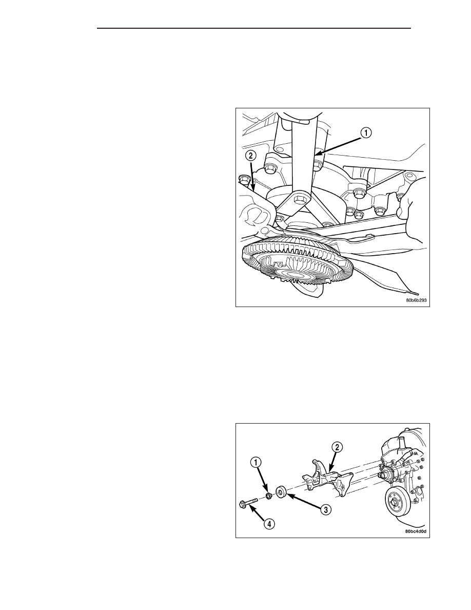
If equipped with A/C, the generator and A/C compres-
sor along with their common mounting bracket (2)
must be partially removed. Removing generator or A/C
compressor from their mounting bracket is not neces-
sary. Also, discharging A/C system is not necessary.
Do not remove any refrigerant lines from A/C com-
pressor.
WARNING: THE A/C SYSTEM IS UNDER PRES-
SURE
EVEN
WITH
ENGINE
OFF.
REFER
TO
REFRIGERANT WARNINGS IN GROUP 24, HEAT-
ING AND AIR CONDITIONING.
1. Disconnect battery negative cable.
7 - 46
ENGINE
ND
2. Partially drain cooling system (Refer to 7 - COOL-
ING - STANDARD PROCEDURE).
3. Remove upper radiator hose clamp and hose at
radiator.
4. Unplug wiring harness from A/C compressor.
5. Remove air cleaner assembly.
6. Remove accessory drive belt (Refer to 7 - COOL-
ING/ACCESSORY
DRIVE/DRIVE
BELTS
-
REMOVAL).
7. Remove bracket-to-intake manifold bolts.
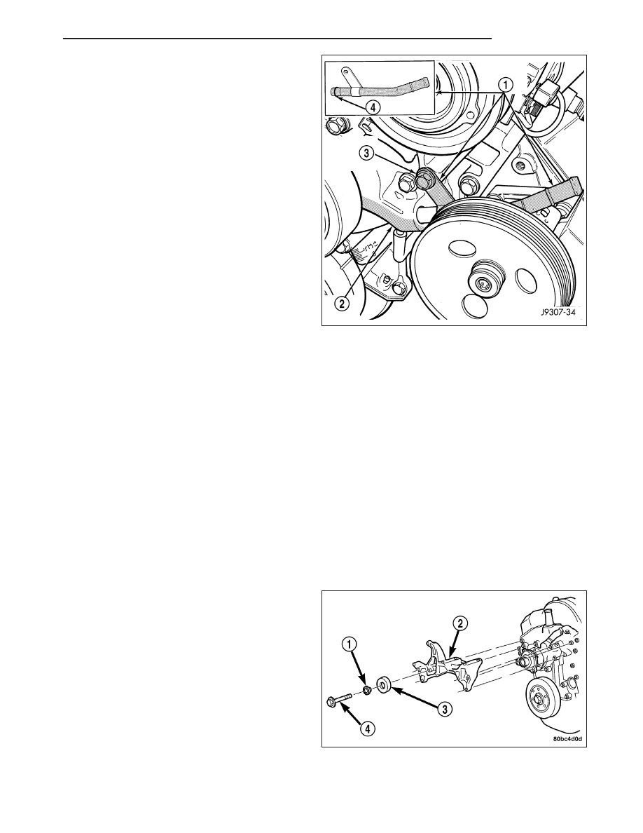
8. The drive belt idler pulley must be removed to gain
access to one of A/C compressor/generator bracket
mounting bolts (3). Remove idler pulley bolt and
remove idler pulley.
9. Remove oil dipstick tube mounting bol (3) at side of
A/C-generator mounting bracket.
10. Disconnect throttle body cables.
11. Remove heater hose clamp and heater hose from
heater hose coolant return tube.
12. Remove heater hose coolant return tube mounting
bolt and remove tube from engine. Discard the old tube O-ring.
13. Remove six bracket bolts.
14. Lift and position generator and A/C compressor (along with their common mounting bracket) to gain access to
bypass hose. A block of wood may be used to hold assembly in position.
15. Loosen and position both hose clamps to center of bypass hose. Remove hose from vehicle.
INSTALLATION
WITHOUT AIR CONDITIONING
1. Position bypass hose clamps to center of hose.
2. Install bypass hose to engine.
3. Secure both hose clamps.
4. Fill cooling system (Refer to 7 - COOLING - STANDARD PROCEDURE).
5. Start and warm the engine. Check for leaks.
WITH AIR CONDITIONING
1. Position bypass hose clamps to center of hose.
2. Install bypass hose to engine.
3. Secure both hose clamps.
4. Install generator-A/C mounting bracket assembly to
engine. Tighten bolts (number 1 and 2 ) to 54 N·m
(40 ft. lbs.) torque. Tighten bolts (number 3 ) to 40
N·m (30 ft. lbs.) torque.
ND
ENGINE
7 - 47
Нет комментариевНе стесняйтесь поделиться с нами вашим ценным мнением.
Текст