Chrysler Le Baron, Dodge Dynasty, Plymouth Acclaim. Manual — part 292
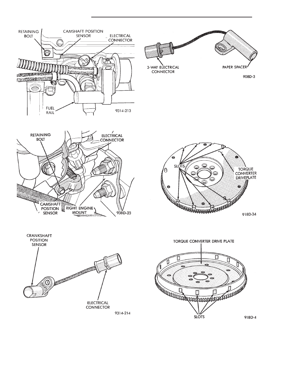
Basic timing is set by the position of the last slot
in each group. Once the powertrain control module
(PCM) senses the last slot, it determines crankshaft
position (which piston will next be at TDC) from the
camshaft position sensor input. The 4 pulses generated
by the crankshaft position sensor represent the 69°,
49°, 29°, and 9° BTDC marks. It may take the PCM one
engine revolution to determine crankshaft position
during cranking.
The PCM uses the camshaft position sensor to deter-
mine injector sequence. The PCM determines igni-
Fig. 20 Camshaft Position Sensor Location—Turbo
III Engines
Fig. 21 Camshaft Position Sensor Location—3.3L
and 3.8L Engines
Fig. 22 Crankshaft Position Sensor—Turbo III
Engine
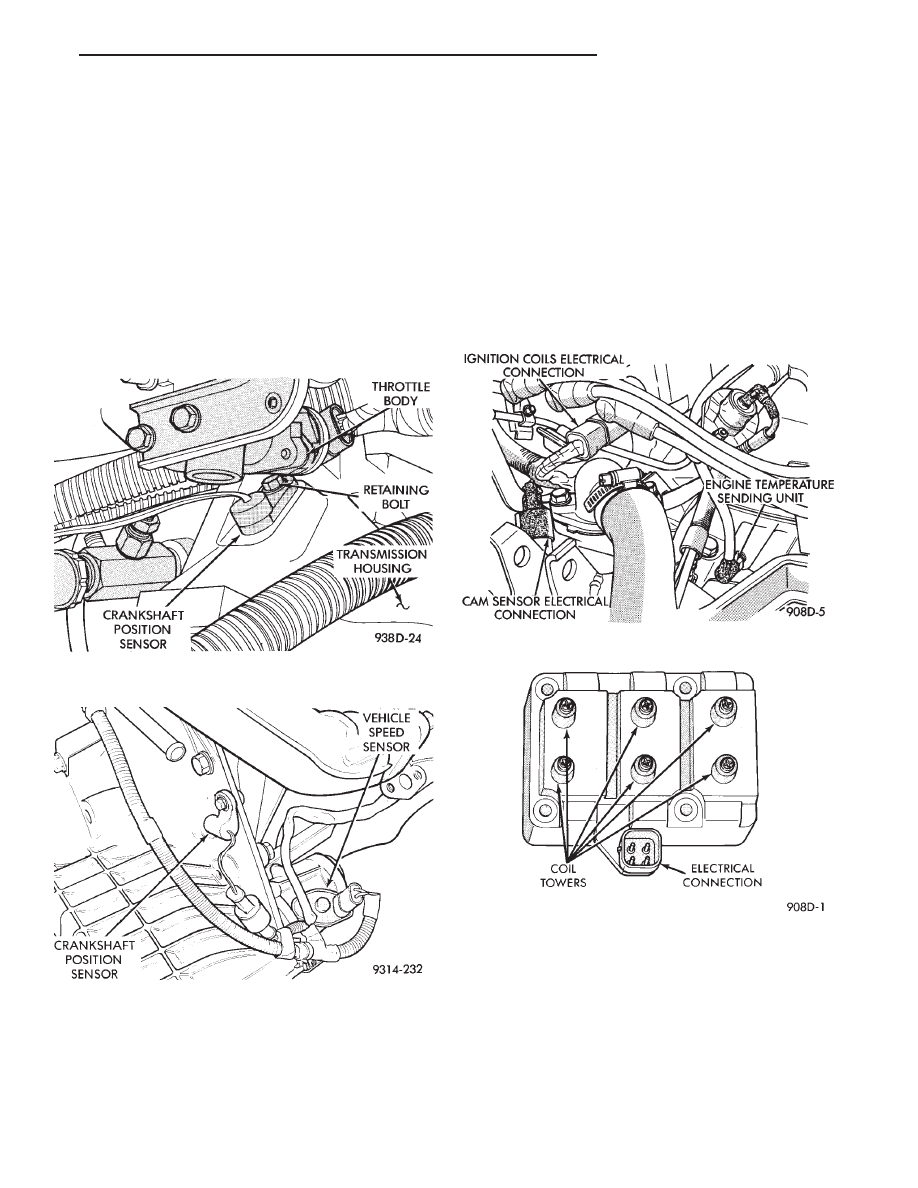
Fig. 23 Crankshaft Position Sensor—3.3L and 3.8L
Engines
Fig. 24 Timing Slots in Transaxle Driveplate—Turbo
III Engine
Fig. 25 Timing Slots in Transaxle Driveplate—3.3L
and 3.8L Engines
8D - 30
IGNITION SYSTEMS
Ä
tion timing from the crankshaft position sensor. Once
crankshaft position has been determined, the PCM
begins energizing the injectors in sequence.
On Turbo III engines, the crankshaft position sensor
is located in the transaxle housing, below the throttle
body (Fig. 26). On 3.3L and 3.8L engines, the crank-
shaft position sensor is located in the transaxle hous-
ing (Fig. 27).
The bottom of the sensor is positioned next to the
drive plate. The distance between the bottom of
sensor and the drive plate is critical to the op-
eration of the system. When servicing the crank-
shaft
sensor,
refer
to
the
3.3L
Ignition
System—Service
Procedures
section
in
this
Group.
IGNITION COIL
WARNING: THE DIRECT IGNITION SYSTEM GENER-
ATES APPROXIMATELY 40,000 VOLTS. PERSONAL
INJURY COULD RESULT FROM CONTACT WITH
THIS SYSTEM.
The 3.3L and 3.8L coil assembly consists of 3 coils
molded together (Fig. 28). The assembly is mounted
on the intake manifold. The 2.2L Turbo III coil as-
sembly consists of 2 coils molded together (Fig. 29).
The assembly is mounted at the front of the engine.
For all engines, the number of each coil appears on
the front of the coil pack.
High tension leads route to each cylinder from the
coil. The coil fires two spark plugs every power
stroke. One plug is the cylinder under compression,
the other cylinder fires on the exhaust stroke. The
PCM determines which of the coils to charge and fire
at the correct time.
On 3.3L and 3.8L engines, coil one fires cylinders 1
and 4, coil two fires cylinders 2 and 5, coil three fires
cylinders three and six.
Fig. 28 Coil Pack—2.2L Turbo III Engine
Fig. 29 Coil Pack—3.3L and 3.8L Engines
Fig. 26 Crankshaft Position Sensor Location—Turbo
III Engines
Fig. 27 Crankshaft Position Sensor Location—3.3L
and 3.8L Engines
Ä
IGNITION SYSTEMS
8D - 31
The coil’s low primary resistance allows the PCM to
fully charge the coil for each firing.
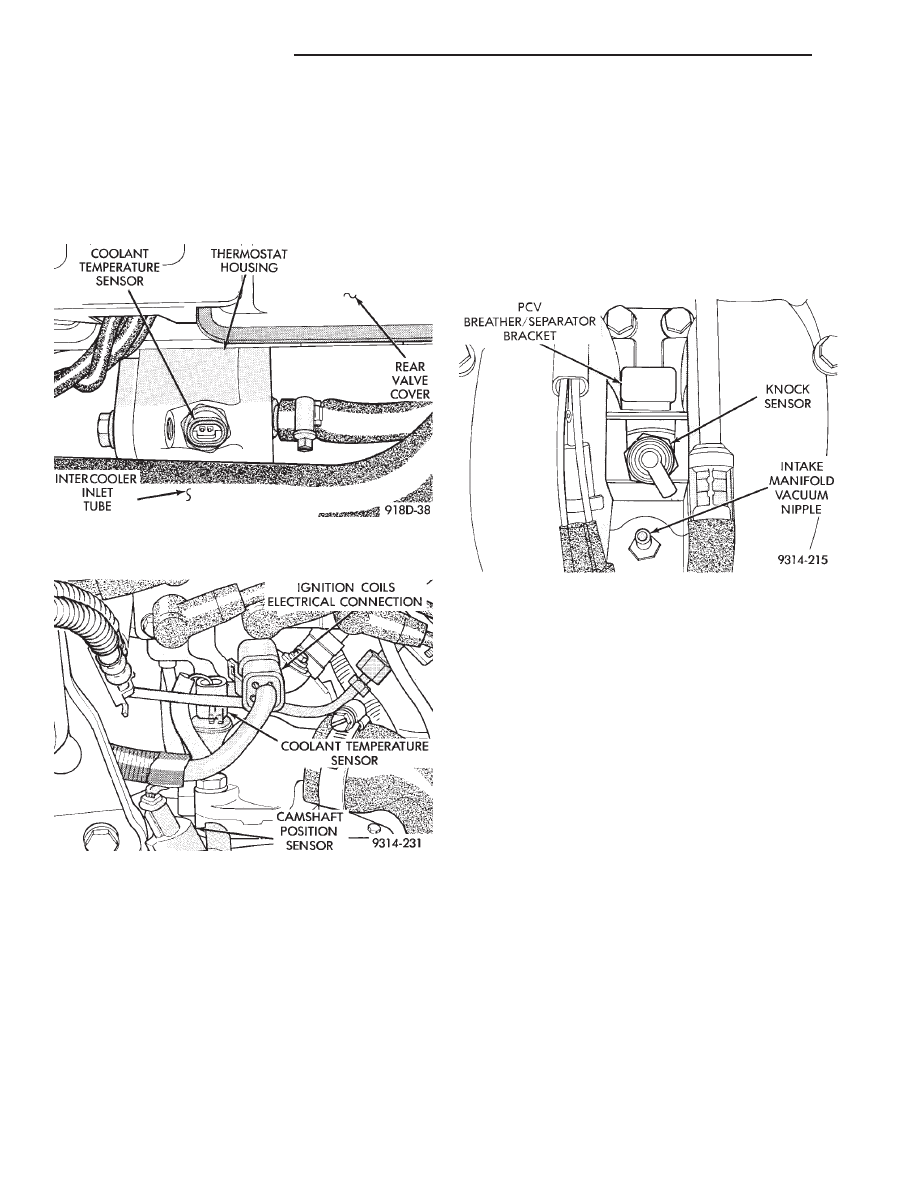
COOLANT TEMPERATURE SENSOR
On 2.2L Turbo III engines, the coolant temperature
sensor is installed into the thermostat housing (Fig. 30).
On 3.3L and 3.8L engines, the coolant temperature sensor
is located next to the thermostat housing (Fig. 31).
The coolant temperature sensor provides an input
voltage to the powertrain control module (PCM). The
sensor is a variable resistance (thermistor) with a
range of -40°C to 130°C (-40°F to 265°F). As coolant
temperature varies, the sensor resistance changes,
resulting in a different input voltage to the PCM.
The PCM contains different spark advance schedules
for cold and warm engine operation. The schedules reduce
engine emission and improve driveability.
The PCM demands slightly richer air-fuel mixtures
and higher idle speeds until the engine reaches normal
operating temperature.
The coolant sensor input is also used for cooling
fan control.
KNOCK SENSOR—TURBO III ENGINE
Turbo III engines use a knock sensor. The sensor gen-
erates a signal when spark detonation occurs in the
combustion chambers. The sensor is mounted on the in-
take manifold behind the PCV breather (Fig. 32). The
sensor provides input voltage used by the powertrain
control module (PCM) to modify spark advance and
boost schedules in order to eliminate detonation.
MANIFOLD ABSOLUTE PRESSURE (MAP) SENSOR
The MAP sensor reacts to absolute pressure in the
intake manifold and provides an input voltage to the
powertrain control module (PCM). As engine load
changes, manifold pressure varies. The changes in
engine load cause the MAP output voltage to change.
The change in MAP sensor output voltage results in
a different input voltage to the PCM.
The input voltage level supplies the PCM with infor-
mation relating to ambient barometric pressure during
engine start-up (cranking) and engine load while its op-
erating. The PCM uses this input along with inputs
from other sensors to adjust air-fuel mixture.
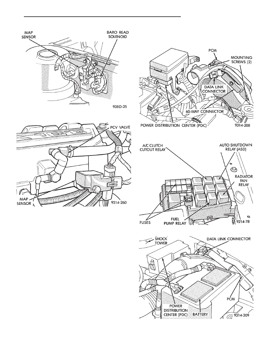
On Turbo III engines, the MAP sensor is mounted
to the front right fender (Fig. 33) On 3.3L and 3.8L
engines, the MAP sensor (Fig. 34) is mounted to the
side of the intake manifold, below the positive crank-
case ventilation (PCV) valve. The sensor is connected
to the PCM electrically.
AUTO SHUTDOWN (ASD) RELAY AND FUEL PUMP
RELAY
The powertrain control module (PCM) operates the
auto shutdown (ASD) relay and fuel pump relay
through one ground path. The PCM operates the re-
lays by switching the ground path on and off. Both
relays turn on and off at the same time.
Fig. 32 Knock Sensor—Turbo III Engine
Fig. 30 Coolant Temperature Sensor—Turbo III En-
gines
Fig. 31 Coolant Temperature Sensor—3.3L and 3.8L
Engines
8D - 32
IGNITION SYSTEMS
Ä
The ASD relay connects battery voltage to the fuel
injector and ignition coil. The fuel pump relay con-
nects battery voltage to the fuel pump and oxygen
sensor heating element.
The PCM turns the ground path off when the igni-
tion switch is in the Off position. Both relays are off.
When the ignition switch is in the On or Crank po-
sition, the PCM monitors the camshaft position sen-
sor and crankshaft position sensor signals. From
these inputs, the PCM determines engine speed and
ignition timing (coil dwell). If the PCM does not re-
ceive a camshaft position sensor signal when the ig-
nition switch is in the Run position, it will de-
energize both relays. When the relays are de-
energized, battery voltage is not supplied to the fuel
injector, ignition coil, fuel pump and oxygen sensor
heating element.
On AC, AG, AJ and AY models, the ASD relay and
fuel pump relay are located in the power distribution
center (Fig. 35, 36, 37, or 38).
On AA and AP models, the ASD relay and fuel
pump relay are mounted on the drivers side fender
well, next to the strut tower (Fig. 39).
Fig. 33 MAP Sensor—Turbo III Engine
Fig. 34 Map Sensor—3.3L and 3.8L Engines
Fig. 35 Power Distribution Center (PDC) (AC Body)
Fig. 36 Relay Identification (AC Body)
Fig. 37 Power Distribution Center (PDC)
(AG and AJ Body)
Ä
IGNITION SYSTEMS
8D - 33
Нет комментариевНе стесняйтесь поделиться с нами вашим ценным мнением.
Текст