Chrysler Le Baron, Dodge Dynasty, Plymouth Acclaim. Manual — part 293
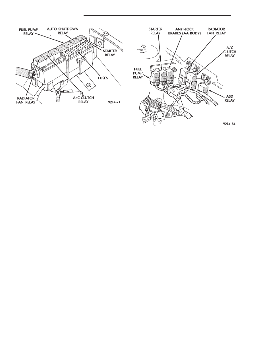
Fig. 39 Relay Identification (AA and AP Bodies)
Fig. 38 Relay Identification (AG and AJ Body)
8D - 34
IGNITION SYSTEMS
Ä
2.2L TURBO III, 3.3L AND 3.8L IGNITION SYSTEM—DIAGNOSTIC PROCEDURES
INDEX
page
page
Check Coil Test—3.3L and 3.8L Engines
. . . . . . 36
Check Coil Test—Turbo III Engine
. . . . . . . . . . . 35
Coolant Temperature Sensor Test
. . . . . . . . . . . . 38
Crankshaft Position Sensor and Camshaft Position
Sensor Tests
. . . . . . . . . . . . . . . . . . . . . . . . . . 38
Failure to Start Test
. . . . . . . . . . . . . . . . . . . . . . 37
Failure to Start Test—Turbo III Engine
. . . . . . . . 36
Manifold Absolute Pressure (MAP) Sensor Test
. 38
Testing for Spark at Coil—3.3L and 3.8L Engines . 36
Testing for Spark at Coil—Turbo III Engine
. . . . . 35
TESTING FOR SPARK AT COIL—TURBO III ENGINE
WARNING: THE DIRECT IGNITION SYSTEM GENER-
ATES APPROXIMATELY 40,000 VOLTS. PERSONAL
INJURY COULD RESULT FROM CONTACT WITH
THIS SYSTEM.
The coil pack contains 2 independent coils. Each
coil must be checked individually.
CAUTION: Spark plug wire damage may occur if the
spark plug is moved more than 1/4 inch away from
the engine ground.
Remove the cable from number 1 spark plug. Insert
a clean spark plug into the spark plug boot, and
ground plug to the engine (Fig. 1).
CAUTION: Spark plug wire damage may occur if the
spark plug is moved more than 1/4 inch away from
the engine ground.
Crank the engine and look for spark across the
electrodes of the spark plug. Repeat the above test
for the remaining cylinders. If there is no spark dur-
ing the cylinder tests, proceed to the failure to start
test.
If one or more cylinders have irregular, weak, or
no spark, proceed to Check Coil Test.
CHECK COIL TEST—TURBO III ENGINE
Cylinders 1 & 4, and 2 & 3 are grouped together.
(1) Remove the ignition cables and measure the
resistance of the cables. Resistance must be between
3,000 to 12,000 ohms per foot of cable. Replace any
cable not within tolerance.
(2) Disconnect the electrical connector from the coil
pack (Fig. 2).
(3) Measure the primary resistance of each coil. At
the coil, connect an ohmmeter between the B+ pin and
the pin corresponding to the cylinders in question (Fig.
3). Resistance on the primary side of each coil should be
0.5-0.7 ohm. Replace the coil if resistance is not within
tolerance.
(4) Remove ignition cables from the secondary tow-
ers of the coil. Measure the secondary resistance of the
coil between the towers of each individual coil
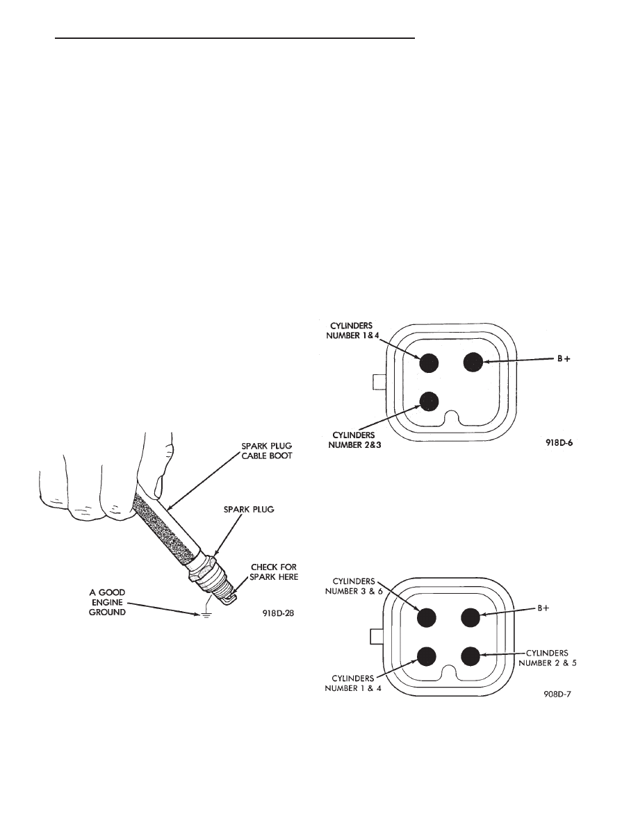
Fig. 1 Testing For Spark
Fig. 2 Ignition Coil Electrical Connection—Turbo III
Engine
Fig. 3 Ignition Coil Terminal Identification
Ä
IGNITION SYSTEMS
8D - 35
(Fig. 4). Secondary resistance should be 11,600 to
15,800 ohms. Replace the coil if resistance is not
within tolerance.
FAILURE TO START TEST—TURBO III ENGINE
(1) Determine that sufficient battery voltage (12.4
volts nominal) is present for the cranking and igni-
tion systems.
(2) Connect a voltmeter to the wiring harness coil
connector at the B+ pin (Fig. 5).
(3) Crank the engine for 5 seconds while monitor-
ing the voltage at the B+ connector terminal. If the
voltage remains near zero during the entire period of
cranking, check the auto shutdown relay and PCM.
Refer to DRBII scan tool and the appropriate Power-
train Diagnostic Procedures manual. Refer to Group
14 for description of On Board Diagnostics.
(4) If voltage is at near-battery voltage, and drops
to zero after 1-2 seconds of cranking, check the cam-
shaft position sensor and crankshaft position sensor
and their circuits. Refer to the DRBII scan tool and
the appropriate Powertrain Diagnostic Procedure
manual. Refer to Group 14 for a description of On-
Board Diagnostics.
(5) If voltage remains at near-battery voltage dur-
ing the entire 5 seconds, turn the key off, remove the
PCM 60-way connector. Check the 60-way for any
terminals loose from the connector (push-out).
TESTING FOR SPARK AT COIL—3.3L AND 3.8L
ENGINES
WARNING: THE ENGINE DIRECT IGNITION SYSTEM
GENERATES APPROXIMATELY 40,000 VOLTS. PER-
SONAL INJURY COULD RESULT FROM CONTACT
WITH THIS SYSTEM.
The coil pack contains 3 independent coils. Each coil
must be checked individually.
CAUTION: Spark plug wire damage may occur if the
spark plug is moved more than 1/4 inch away from the
engine ground.
Remove the cable from number 2 spark plug. Insert a
clean spark plug into the spark plug boot, and ground
plug to the engine (Fig. 1).
Crank the engine and look for spark across the
electrodes of the spark plug. Repeat the above test for
the five remaining cylinders. If there is no spark
during all cylinder tests, proceed to the failure to start
test.
If one or more tests indicate irregular, weak, or no
spark, proceed to Check Coil Test.
WARNING: THE DIRECT IGNITION SYSTEM GENER-
ATES APPROXIMATELY 40,000 VOLTS. PERSONAL
INJURY COULD RESULT FROM CONTACT WITH THIS
SYSTEM.
CHECK COIL TEST—3.3L AND 3.8L ENGINES
Coil one fires cylinders 1 and 4, coil two fires
cylinders 2 and 5, coil three fires cylinders three
and six.
Each coil tower is labeled with the number of the
corresponding cylinder.
(1) Remove the ignition cables and measure the
resistance of the cables. Resistance must be between
3,000 to 12,000 ohms per foot of cable. Replace any
cable not within tolerance.
(2) Disconnect the electrical connector from the coil
pack (Fig. 6).
(3) Measure the primary resistance of each coil. At
the coil, connect an ohmmeter between the B+ pin and
the pin corresponding to the cylinders in question (Fig.
7). Resistance on the primary side of each coil should be
0.5 - 0.7 ohm. Replace the coil if resistance is not within
tolerance.
(4) Remove ignition cables from the secondary tow-
ers of the coil. Measure the secondary resistance of the
coil between the towers of each individual coil (Fig. 8).
Refer to the Coil Specifications Chart in the Specifica-
tions section of this group. Replace the coil if resistance
is not within tolerance.
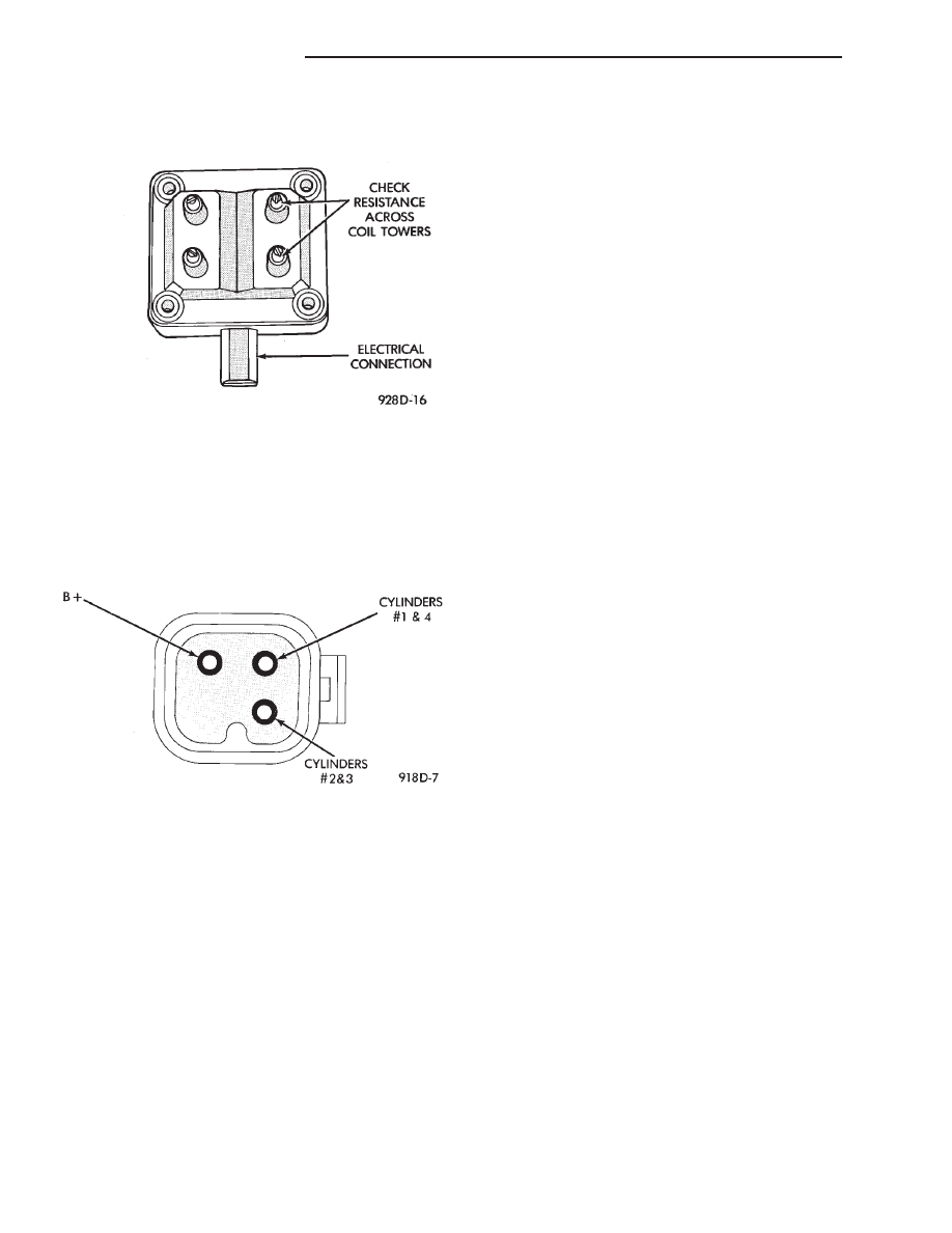
Fig. 4 Checking Ignition Coil Secondary
Resistance—Turbo III Engines
Fig. 5 Wiring Harness Coil Connector—Turbo III
Engine
8D - 36
IGNITION SYSTEMS
Ä

FAILURE TO START TEST
This no-start test checks the camshaft position sen-
sor and crankshaft position sensor.
The powertrain control module (PCM) supplies 8.0
volts to the camshaft position sensor and crankshaft
position sensor through one circuit. If the 8.0-volt
supply circuit shorts to ground, neither sensor will
produce a signal (output voltage to the PCM).
When the ignition key is turned and left in the On
position, the PCM automatically energizes the auto
shutdown (ASD) relay. However, the PCM de-energizes
the relay within one second because it has not received
a crankshaft position sensor signal indicating engine
rotation.
During cranking, the ASD relay will not energize
until the PCM receives a crankshaft signal. Secondly,
the ASD relay remains energized only if the PCM
senses a camshaft position sensor signal immediately
after detecting the crankshaft position sensor signal.
(1) Check battery voltage. Voltage should approxi-
mately 12.66 volts or higher to perform failure to start
test.
(2) Disconnect the harness connector from the coil
pack (Fig. 2).
(3) Connect a test light to the B+ (battery voltage)
terminal of the coil electrical connector and ground.
The wire for the B+ terminal is dark green with a black
tracer.
(4) Turn the ignition key to the ON position. The
test light should flash On and then Off. Do not turn
the Key to off position, leave it in the On position.
(a) If the test light flashes momentarily, the PCM
grounded the auto shutdown (ASD) relay. Proceed to
step 5.
(b) If the test light did not flash, the ASD relay did
not energize. The cause is either the relay or one of
the relay circuits. Use the DRBII scan tool to test the
ASD relay and circuits. Refer to the appropriate
Powertrain Diagnostics Procedure Manual. Refer to
the wiring diagrams section for circuit information.
(5) Crank the engine. If the key was placed in the off
position after step 4, place the key in the On position
before cranking. Wait for the test light to flash once,
then crank the engine.
(a) If the test light momentarily flashes during
cranking, the PCM is not receiving a camshaft posi-
tion sensor signal. Use the DRBII scan tool to test the
camshaft position sensor and sensor circuits. Refer to
the appropriate Powertrain Diagnostics Procedure
Manual. Refer to the wiring diagrams section for
circuit information.
(b) If the test light did not flash during cranking,
unplug the camshaft position sensor connector. Turn
the ignition key to the off position. Turn the key to
the On position, wait for the test light to momen-
tarily flash once, then crank the engine. If the test
light momentarily flashes, the camshaft position
sensor is shorted and must be replaced. If the light
did not flash, the cause of the no-start is in either the
crankshaft position sensor/camshaft position sensor
8.0-volt supply circuit, or the crankshaft position
sensor 5-volt output or ground circuits. Use the
DRBII scan tool to test the crankshaft position sen-
sor and the sensor circuits.
Fig. 6 Ignition Coil Electrical Connection
Fig. 7 Ignition Coil Terminal Identification
Fig. 8 Checking Ignition Coil Secondary Resistance
Ä
IGNITION SYSTEMS
8D - 37
Нет комментариевНе стесняйтесь поделиться с нами вашим ценным мнением.
Текст