Chrysler Le Baron, Dodge Dynasty, Plymouth Acclaim. Manual — part 577
BALANCE SHAFTS CARRIER ASSEMBLY
REMOVAL
The following components will remain intact dur-
ing carrier removal. Gear cover, gears, balance shafts
and the rear cover.
(1) Remove chain cover and driven balance shaft
chain sprocket screw.
(2) Loosen tensioner pivot and adjusting screws,
move driven balance shaft inboard through driven
chain sprocket. Sprocket will hang in lower chain
loop.
(3) Remove carrier to crankcase attaching bolts to
remove carrier.
INSTALLATION
Balance shaft and carrier assembly installation is
the reverse of the removal procedure. During instal-
lation crankshaft to balance shaft timing must be
established.
TIMING
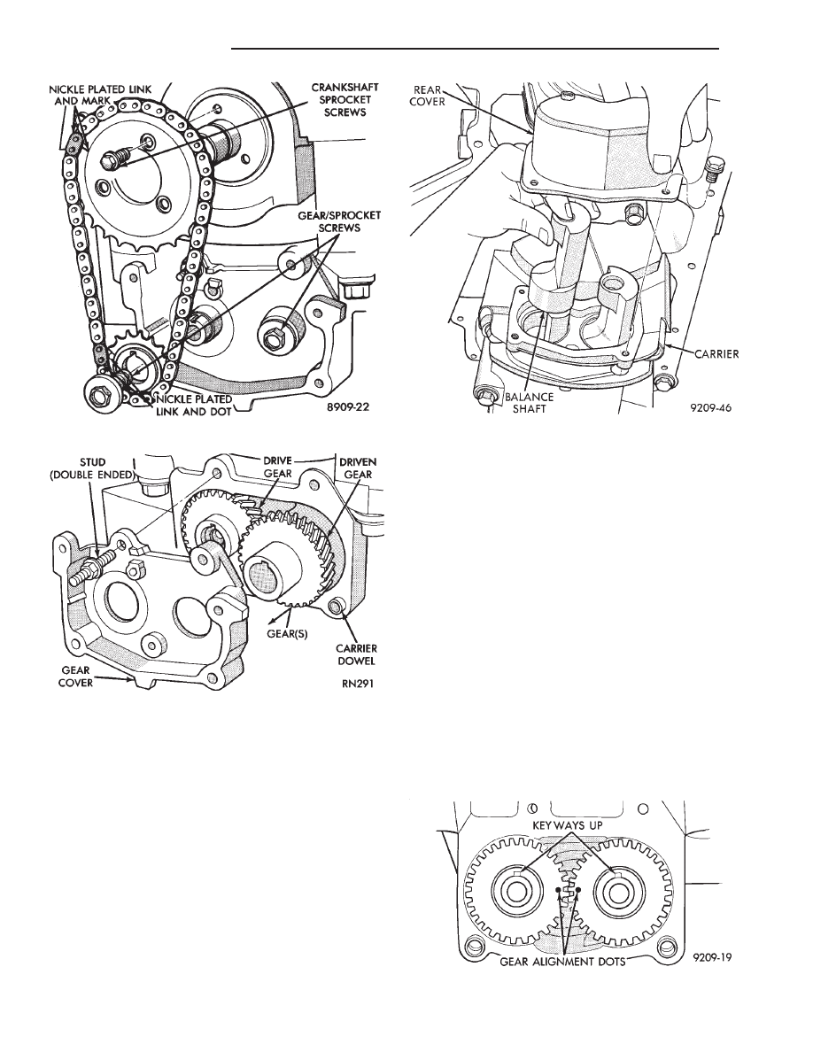
(1) With balance shafts installed in carrier (Fig. 19)
position carrier on crankcase and install six attaching
bolts and tighten to 54 N
Im (40 ft. lbs.).
(2) Turn balance shafts until both shaft key ways are
up Parallel to vertical centerline of engine. Install
short hub drive gear on sprocket driven shaft and long
hub gear on gear driven shaft. After installation gear
and balance shaft keyways must be up with gear
timing marks meshed as shown in (Fig. 20).
(3) Install gear cover and tighten double ended
stud/washer fastener to 12 N
Im (105 in. lbs.).
(4) Install crankshaft sprocket and tighten socket
head torx screws to 13 N
Im (130 in. lbs.).
Fig. 20 Gear Timing
Fig. 17 Drive Chain and Sprockets
Fig. 18 Gear Cover and Gears
Fig. 19 Balance Shaft(s) Remove/Install
9 - 46
2.2/2.5L ENGINE
Ä
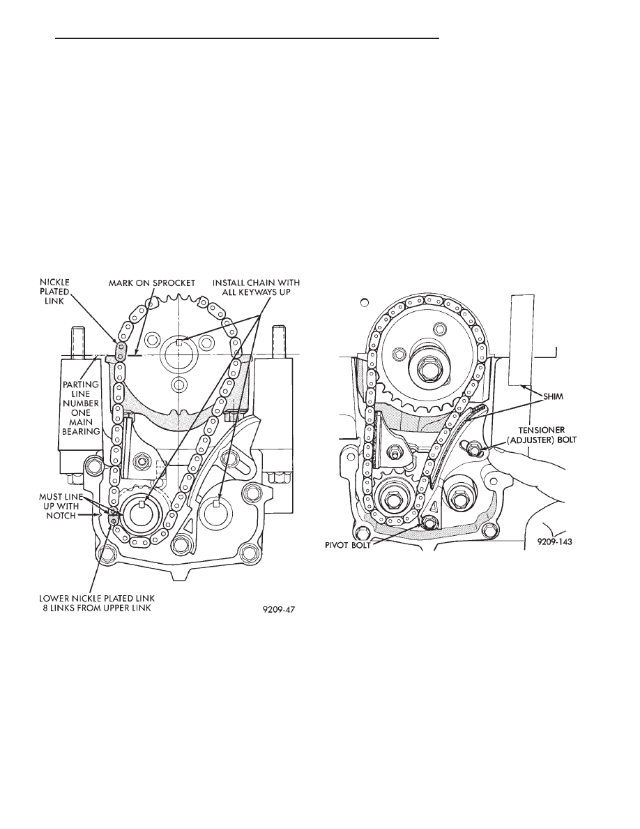
(5) Turn crankshaft until number one cylinder is
at Top Dead Center (TDC). The timing marks on the
chain sprocket should line up with the parting line
on the left side of number one main bearing cap.
(Fig. 21).
(6) Place chain over crankshaft sprocket so that
the nickel plated link of the chain is over the timing
mark on the crankshaft sprocket (Fig. 21).
(7) Place balance shaft sprocket into the timing
chain (Fig. 17) so that the timing mark on the
sprocket (yellow dot) mates with the (lower) nickel
plated link on the chain
(8) With balance shaft keyways pointing up 12
o’clock) slide the balance shaft sprocket onto the nose
of the balance shaft. The balance shaft may have to
be pushed in slightly to allow for clearance.
THE TIMING MARK ON THE SPROCKET,
THE (LOWER) NICKEL PLATED LINK, AND
THE ARROW ON THE SIDE OF THE GEAR
COVER SHOULD LINE UP WHEN THE BAL-
ANCE SHAFTS ARE TIMED CORRECTLY.
(9) If the sprockets are timed correctly install the
balance shaft bolts and tighten to 28 N
Im (250 in.
lbs.). A wood block placed between crankcase and
crankshaft counterbalance will prevent crankshaft
and gear rotation.
CHAIN TENSIONING
(1) Install chain tensioner loosely assembled.
(2) Position guide on double ended stud making sure
tab on the guide fits into slot on the gear cover. Install
and tighten nut/washer assembly to 12 N
Im (105 in.
lbs.).
(3) Place a shim 1mm (.039 inch) thick x 70mm (2.75
inch) long or between tensioner and chain. Push ten-
sioner and shim up against the chain. Apply firm
pressure (5.5 to 6.6 lbs.) directly behind the ad-
justment slot to take up all slack (chain must have
shoe radius contact as shown in Fig. 22).
(4) With the load applied, tighten top tensioner bolt
first, then bottom pivot bolt. Tighten bolts to 12 N
Im
(105 in. lbs.), Remove shim.
(5) Install carrier covers and tighten screws to 12
N
Im (105 in. lbs.).
INTERMEDIATE SHAFT SERVICE
REMOVAL
CAUTION: The oil pump and distributor must be
removed before attempting to remove intermediate
shaft.
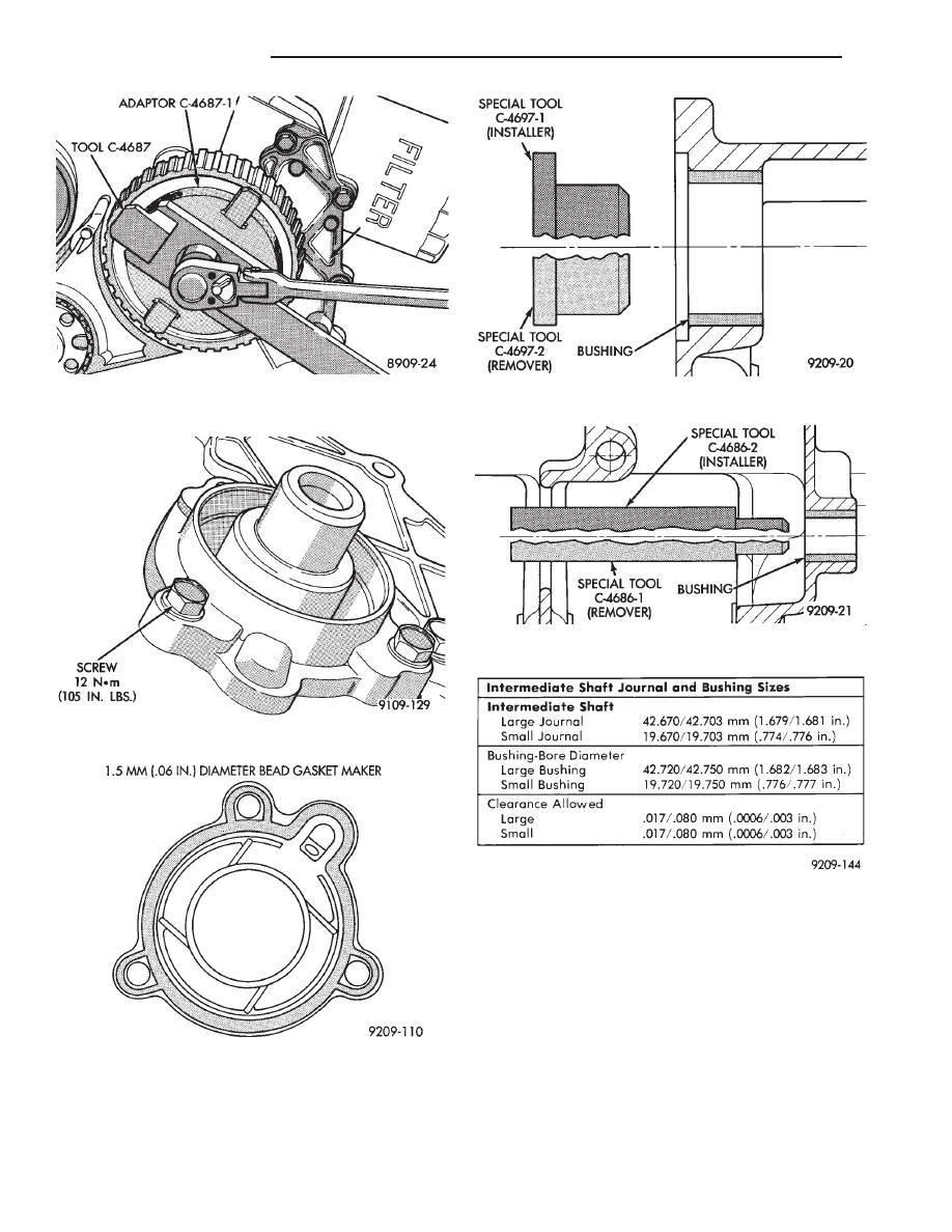
(1) Hold sprocket with Tool C-4687 and adaptor Tool
C-4687-1 when removing or installing screw (Fig. 23).
(2) See Timing System and Seals for intermediate
seal removal and replacement.
(3) Remove retainer screws (Fig. 24).
(4) Remove retainer and lay aside.
(5) Remove intermediate shaft.
Fig. 21 Balance Shaft Timing
Fig. 22 Chain Tension Adjustment
Ä
2.2/2.5L ENGINE
9 - 47
INSTALLATION
(1) Lubricate distributor drive gear when installing.
(2) Apply Mopar Gasket Maker as shown in (Fig.
25) and install intermediate shaft retainer.
(3) Install retaining screws and torque to 12 N
Im
(105 in. lbs.).
INTERMEDIATE SHAFT BUSHING SERVICE
(1) Remove
front
bushing
using
Special
Tool
C-4697-2 with Special Tool Handle C-4171 (Fig. 26).
(2) Install
front
bushing
using
Special
Tool
C-4697-1 and Special Tool Handle C-4171 until tool
is flush with block.
(3) Remove
rear
bushing
using
Special
Tool
C-4686-2 and Special Tool Handle C-4171 (Fig. 27).
(4) Install
rear
bushing
using
Special
Tool
C-4686-1 and Special Tool Handle C-4171 until tool
is flush with block.
Fig. 23 Removing/Installing Intermediate Shaft
Sprocket
Fig. 24 Intermediate Shaft Retainer
Fig. 25 Intermediate Shaft Retainer Sealing
Fig. 26 Intermediate Shaft Bushing, Front
Fig. 27 Intermediate Shaft Bushing—Rear
Fig. 28 Intermediate Shaft Journal Specifications
9 - 48
2.2/2.5L ENGINE
Ä
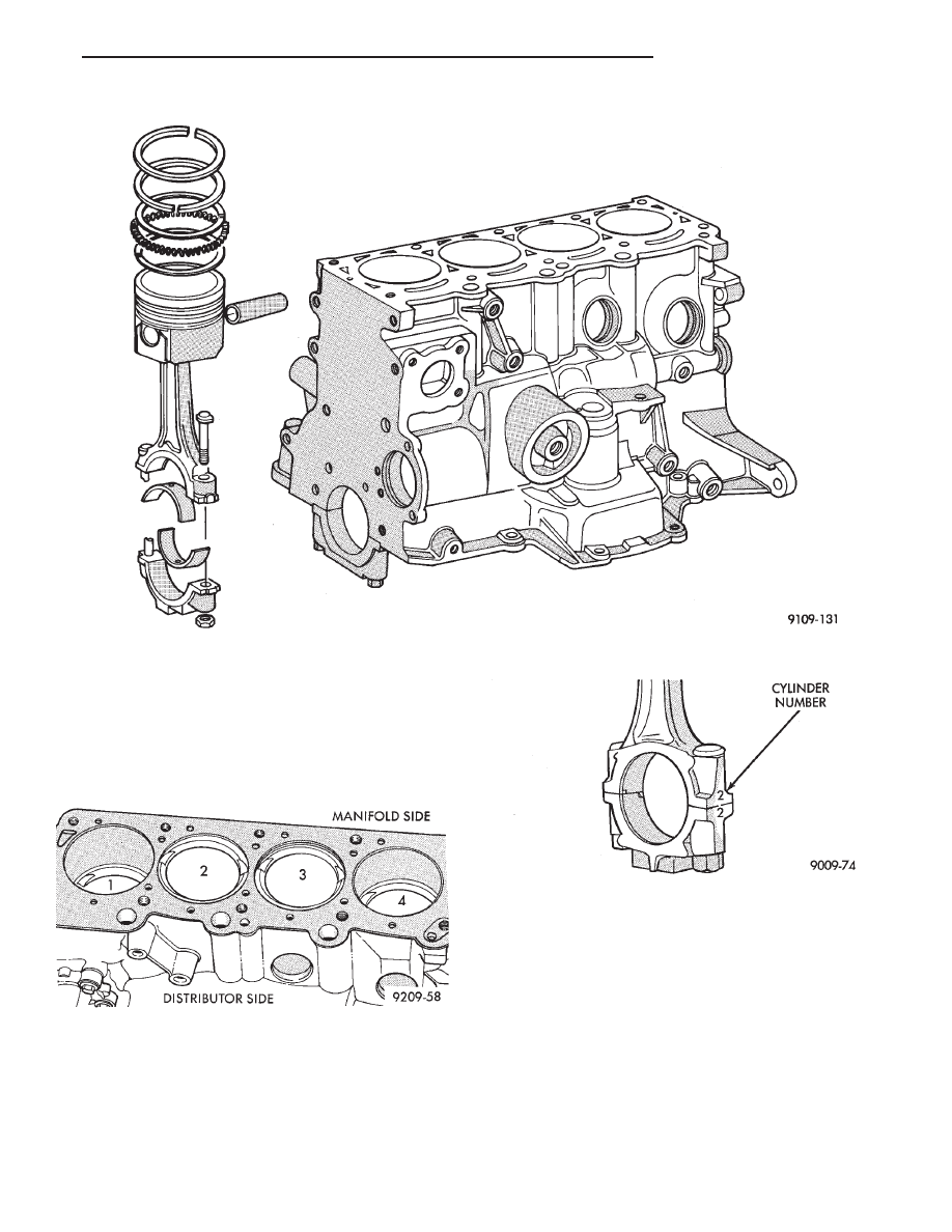
CYLINDER BLOCK, PISTON AND CONNECTING ROD ASSEMBLY SERVICE
PISTON AND CONNECTING ROD—REMOVAL
(1) Remove top ridge of cylinder bores with a reliable
ridge reamer before removing pistons from cylinder
block.Be sure to keep tops of pistons covered
during this operation. Mark piston with matching
cylinder number (Fig. 2).
(2) Remove oil pan. Ensure connecting rods and
connecting rod caps for cylinder identification. Identify
them if necessary (Fig. 3).
(3) Valve relief toward manifold side of engine. Tur-
bocharged engine pistons will have arrow towards
front of engine.
(4) Squirt hole on connecting rod must face timing
belt end of engine.
(5) Pistons and connecting rods must be removed
from top of cylinder block. Rotate crankshaft so that
each connecting rod is centered in cylinder bore.
(6) Remove connecting rod cap. Install connecting
rod bolt protectors on connecting rod bolts (Fig. 4).
Push each piston and rod assembly out of cylinder
bore.
Be careful not to nick crankshaft journals.
(7) After removal, install bearing cap on the mat-
ing rod.
Fig. 1 Cylinder Block, Piston and Connecting Rod Assembly
Fig. 3 Identify Connecting Rod to Cylinder
Fig. 2 Piston Marking
Ä
2.2/2.5L ENGINE
9 - 49
Нет комментариевНе стесняйтесь поделиться с нами вашим ценным мнением.
Текст