Chrysler Le Baron, Dodge Dynasty, Plymouth Acclaim. Manual — part 578

CYLINDER BLOCK CLEANING AND
INSPECTION
(1) Clean cylinder block thoroughly and check all
core hole plugs for evidence of leaking.
(2) If new core plugs are installed, Refer to Engine
Core Oil and Cam Plugs.
(3) Examine block and cylinder bores for cracks or
fractures.
CYLINDER BORE INSPECTION
The cylinder walls should be checked for out-of-
round and taper with Tool C-119 (Fig. 5). The cylin-
der bore out-of-round is 0.050 mm (.002 inch)
maximum and cylinder bore taper is .125 mm (.005
inch) maximum. If the cylinder walls are badly
scuffed or scored, the cylinder block should be re-
bored and honed, and new pistons and rings fitted.
Whatever type of boring equipment is used, boring
and honing operation should be closely coordinated
with the fitting of pistons and rings in order that
specified clearances may be maintained. Refer to
Honing Cylinder Bores outlined in the Standard
Service Procedures for specification and proce-
dures.
Measure the cylinder bore at three levels in direc-
tions A and B (Fig. 5). Top measurement should be
10mm ( 3/8 inch) down and bottom measurement
should be 10mm ( 3/8 inch.) up from bottom of bore.
Refer to (Fig. 6) for specifications.
SIZING PISTONS
Piston and cylinder wall must be clean and dry.
Piston diameter should be measured 90 degrees to
piston pin at size location shown in (Fig. 7). Cylinder
bores should be measured halfway down the cylinder
bore and transverse to the engine crankshaft center
line shown in (Fig. 5). Refer to (Fig. 6) for specifica-
Fig. 5 Checking Cylinder Bore Size
Fig. 6 Piston Size Location and Clearance Chart
Fig. 4 Connecting Rod Protectors
9 - 50
2.2/2.5L ENGINE
Ä

tions. Correct piston to bore clearance must be estab-
lished in order to assure quiet and economical
operation.
Chrysler engines use pistons designed specifically for
each engine model. Clearance and sizing locations vary
with respect to engine model.
Pistons and cylinder bores should be measured
at normal room temperature, 70°F. (21°C).
Fig. 7 Piston Installation and Sizing Information
Fig. 8 N.A. (Naturally Aspirated) Pistons
Fig. 9 2.2L Turbo III Piston
Fig. 10 Piston Pin Lock Ring Removal
Notch—Turbo III Engine
Ä
2.2/2.5L ENGINE
9 - 51
PISTON PINS
DISASSEMBLY
Turbo III engine piston-pin-connecting rod assem-
blies should not be disassembled unless a malfunc-
tion is present or a damaged assembly component is
to be replaced.
WARNING: APPROVED SAFETY GLASSES
MUST
BE
WORN
DURING
PISTON
LOCK
RING REMOVAL OR INSTALLATION TO PRE-
VENT
POSSIBLE
INJURY
FROM
FLYING
PARTS.
(1) Carefully, remove piston pin lock rings from
piston, using a small screwdriver in removal notch
(Fig. 10).
(2) Discard used lock ring.
(3) Following lock ring removal, attempt to slide
pin out of piston. If pin does not slide out freely by
hand;
• Check for burr on outer edge of lock ring groove. If
one is present, carefully scrape burr away with a
knife or other hand tool, being careful not to damage
lock ring retaining groove.
(4) Slide out piston pin to complete disassembly.
(5) Inspect components, discard damaged or exces-
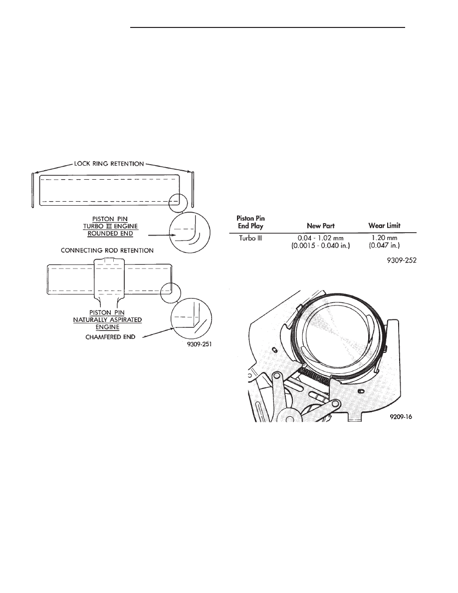
sively worn parts refer to specifications (Fig. 12). If a
piston is replaced, a new pin should be used.
PISTON PINS
REASSEMBLY
(1) Different lock rings are used for turbocharged
engine applications. Consult the Service Note, pro-
vided with the lock ring service package, to select
the correct lock rings from the package for your ap-
plication.
(2) Carefully, install one NEW lock ring with gap
towards piston top in lock ring groove. Do not rein-
stall used lock rings.
(3) Position connecting rod and slide in lightly oil
piston pinch
(4) Install second NEW lock ring with gap towards
piston top in lock ring groove, use small screwdriver
if needed.
CAUTION:
BOTH
lock
rings
must
be
FULLY
SEATED in lock ring grooves or engine failure will
occur.
(5) Check piston pin end play pin movement be-
tween lock rings in assembly.
PISTON RING—REMOVAL
(1) ID mark on face of upper and intermediate pis-
ton rings must point toward piston crown.
(2) Using a suitable ring expander, remove upper
and intermediate piston rings (Fig. 13).
(3) Remove the upper oil ring side rail, lower oil
ring side rail and then oil ring expander from piston.
(4) Clean ring grooves of any carbon deposits.
Fig. 11 Engine Piston Pins—Turbo III, Naturally
Aspirated and Flexible Fuel Vehicles
Fig. 12 Piston Pin Specifications
Fig. 13 Piston Rings—Removing and Installing
9 - 52
2.2/2.5L ENGINE
Ä

FITTING RINGS
(1) Wipe cylinder bore clean. Insert ring and push
down with piston to ensure it is square in bore. The
ring gap measurement must be made with the ring
positioning at least 12mm (.50 inch) from bottom of
cylinder bore. Check gap with feeler gauge (Fig. 14).
Refer to specifications (Fig. 16 and 17).
(2) Check piston ring to groove clearance: (Fig. 15).
Refer to specification (Figs. 16 and 17).
PISTON RINGS—INSTALLATION
(1) The No. 1 and No. 2 piston rings have a differ-
ent cross section. Install rings with manufacturers
I.D. mark facing up, to the top of the piston (Fig. 13).
CAUTION: Install piston rings in the following or-
der:
(a) Oil ring expander.
(b) Upper oil ring side rail.
(c) Lower oil ring side rail.
(d) No. 2 Intermediate piston ring.
(e) No. 1 Upper piston ring.
(2) Install the side rail by placing one end between
the piston ring groove and the expander. Hold end
Fig. 16 Piston Ring Specifications—Turbo III
Fig. 17 Piston Ring Specifications— Naturally
Aspirated and Flexible Fuel Vehicles
Fig. 18 Installing Side Rail
Fig. 14 Piston Ring Gap
Fig. 15 Piston Ring Groove Clearance
Ä
2.2/2.5L ENGINE
9 - 53
Нет комментариевНе стесняйтесь поделиться с нами вашим ценным мнением.
Текст