Chrysler Le Baron, Dodge Dynasty, Plymouth Acclaim. Manual — part 189
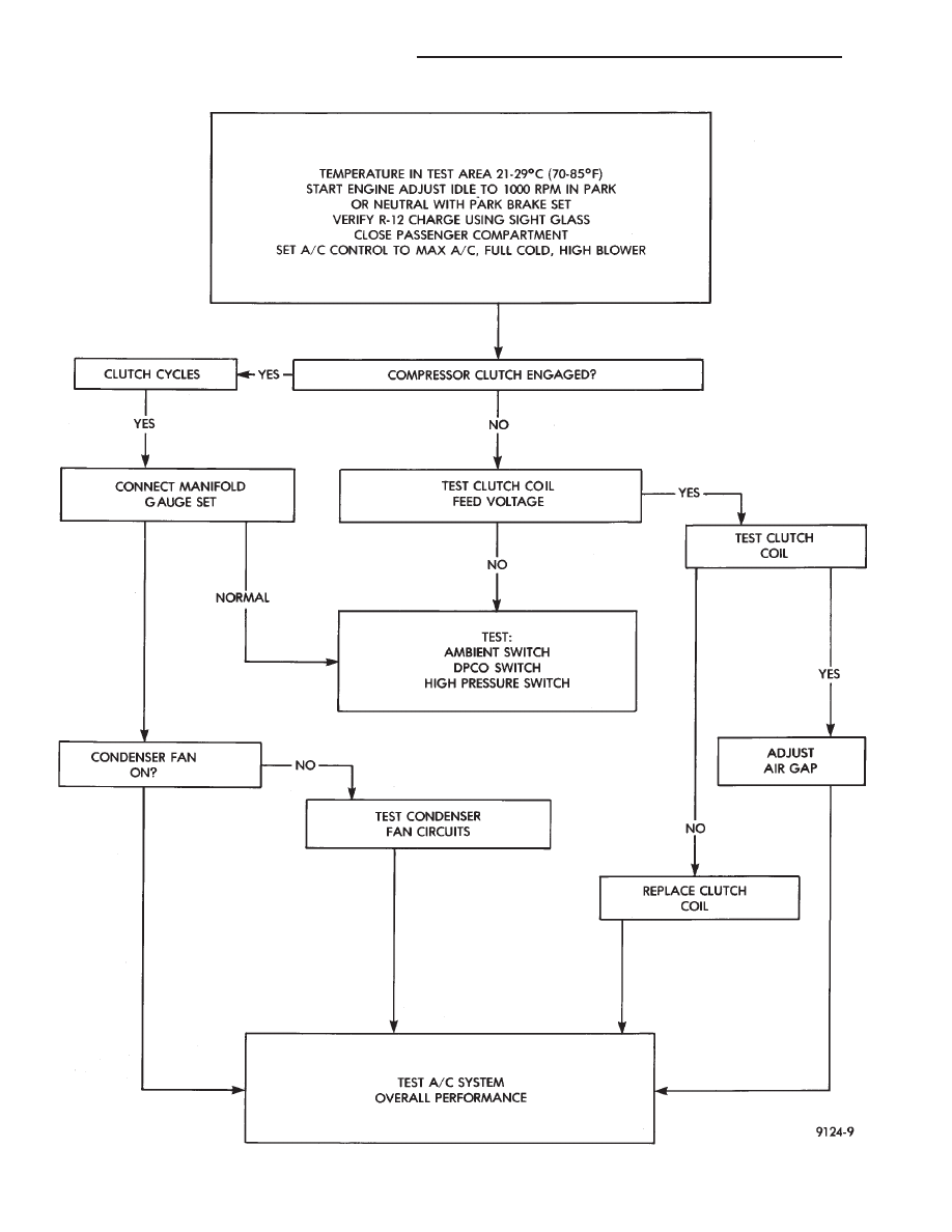
COMPRESSOR CLUTCH DIAGNOSIS—VARIABLE DISPLACEMENT COMPRESSOR—MODEL 6C17
24 - 18
HEATING AND AIR CONDITIONING
Ä

COMPRESSOR CLUTCH/COIL ASSEMBLY
Compressor
assembly
must
be
removed
from
mounting. Refrigerant removal is not necessary to
replace the clutch/coil assembly. Refer to Compressor
Removal and Installation.
On 3.0 liter engine, remove the front lower splash
shield and front engine mount through-bolt. Allow
the engine to swing down to provide access to the
front of the compressor.
On 3.3 liter engine, remove the coolant recovery
bottle to provide access the front of the compressor.
REMOVAL AND INSTALLATION
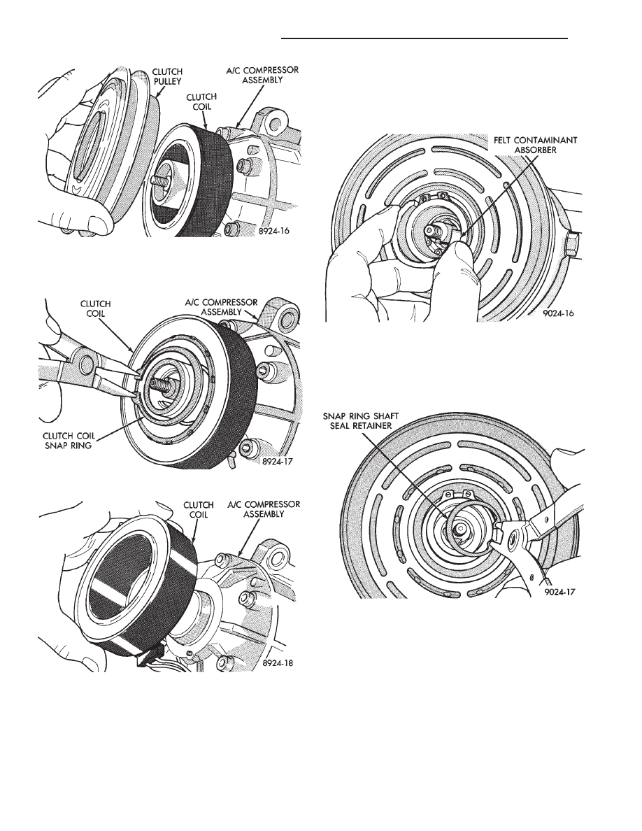
(1) Remove clutch retaining center nut by using
Clutch Plate Holder (6355) (Fig. 4).
(2) Using a Clutch Plate Remover (6354), remove
the clutch front plate from the compressor (Fig. 5).
When installing the front plate, select the proper
shims to achieve .5 to .9 mm (.020 to .035 inch) air
gap to the pulley surface (Fig. 6). To install front
plate, align shaft key to groove in front plate hub.
Push on until it seats, and measure the air gap (Fig.
7).
(3) Remove clutch pulley retaining snap ring (Fig.
7) and pull the pulley from the assembly (Fig. 8).
(4) Remove the clutch coil wire lead strap screw.
(5) Remove clutch coil retaining snap ring (Fig. 10)
and pull the coil from the assembly (Fig. 11). When
installing the clutch coil, align the pin on the front of
Fig. 4 Remove or Install Front Plate Retaining Nut
Fig. 5 Remove Front Plate
Fig. 6 Install Front Plate and Shims
Fig. 7 Measure Front Plate Air Gap
Fig. 8 Remove or Install Pulley Snap Ring
Ä
HEATING AND AIR CONDITIONING
24 - 19
the compressor to the middle hole in the hub of the
coil. Position the pin in the snap ring gap.
To install, reverse the preceding operation.
COMPRESSOR FRONT SHAFT SEAL
REMOVAL
(1) Using a refrigerant recovery machine, remove
the refrigerant from the A/C system.
(2) Remove A/C compressor.
(3) Remove the compressor clutch assembly and
shaft key.
(4) Remove the felt contaminant absorber and re-
tainer (Fig. 1).
(5) Using a mineral spirits based solvent, thor-
oughly clean and dry the seal end of the compressor.
(6) Remove the snap ring shaft seal retainer (Fig.
2). Do not use the old snap ring to assemble.
(7) Using Seal Remover/Installer (6429), remove
the shaft seal (Fig. 3).
INSTALLATION
(1) Lubricate the new shaft seal with refrigerant
oil.
(2) Place Seal Protector (6231) over the end of com-
pressor shaft (Fig. 4). Use the larger flat end of the
remover/installer to push the seal in until it seats.
The snap ring groove should be visible above the seal
(Fig. 5).
(3) Install clutch/coil assembly.
(4) Install compressor.
Fig. 9 Remove or Install Pulley
Fig. 10 Remove or Install Clutch Coil Snap Ring
Fig. 11 Remove or Install Clutch Coil
Fig. 1 Felt Contaminant Absorber
Fig. 2 Shaft Seal Snap Ring
24 - 20
HEATING AND AIR CONDITIONING
Ä

(5) Evacuate and charge the refrigerant system. If
oil loss of 3 ml (1 oz) or greater is suspected, refer to
Oil Level in the Refrigerant Service Procedures sec-
tion.
COMPRESSOR HIGH PRESSURE CUT-OUT SWITCH
The High Pressure Cut Out (HPCO) switch is lo-
cated on the rear cover of the Variable Displacement
Compressor (Fig. 6). The function of the switch is to
disengage the compressor clutch by monitoring the
compressor discharge (high) pressure. The HPCO
Switch is in the same circuit as the Differential Pres-
sure Cut Out (DPCO) switch and Ambient Switch.
DIAGNOSIS
Review Safety Precautions and Warnings before
proceeding with this operation.
Connect a suitable manifold gauge set to the refrig-
erant system service ports. Work area temperature
can not be below 21°C (70°F).
(1) Raise hood of vehicle.
(2) With gear selector in park or neutral, and park
brake set, start engine and allow to idle at 1300 rpm.
(3) Set the A/C controls to A/C and High blower.
(6) If the high pressure gauge reads below 2963
kPa (430 psi)
6138 kPa (20 psi) the compressor
clutch should be engaged.
CAUTION: Do not allow engine to overheat when ra-
diator air flow is blocked.
(7) Block radiator air flow with a suitable cover to
increase the high side pressure to at least 3100 kPa
(450 psi). Compressor clutch should disengage.
(8) Remove cover from front of vehicle to allow
high side pressure to decrease. When pressure drops
below 1826 kPa (265 psi), compressor clutch should
engage.
REMOVAL AND INSTALLATION
(1) Using a refrigerant recovery machine, remove
the refrigerant from the A/C system.
Fig. 3 Remove Shaft Seal
Fig. 4 Shaft Seal Protector
Fig. 5 Install Shaft Seal
Fig. 6 Variable Displacement Compressor—Model
6C17
Ä
HEATING AND AIR CONDITIONING
24 - 21
Нет комментариевНе стесняйтесь поделиться с нами вашим ценным мнением.
Текст