Chrysler Le Baron, Dodge Dynasty, Plymouth Acclaim. Manual — part 188
VARIABLE DISPLACEMENT COMPRESSOR DIAGNOSIS
24 - 14
HEATING AND AIR CONDITIONING
Ä

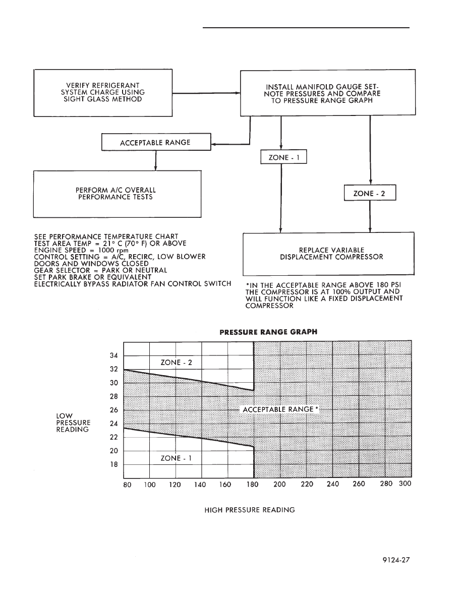
REFRIGERANT SYSTEM DIAGNOSIS—VARIABLE DISPLACEMENT COMPRESSOR
Ä
HEATING AND AIR CONDITIONING
24 - 15
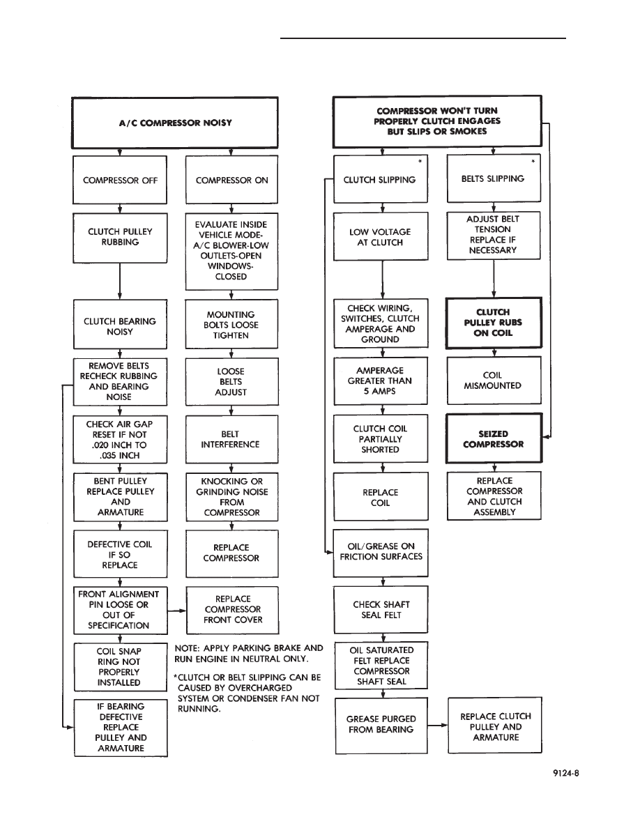
COMPRESSOR NOISE AND COMPRESSOR CLUTCH DIAGNOSIS
24 - 16
HEATING AND AIR CONDITIONING
Ä
(2) The appropriate Powertrain Diagnostic Proce-
dures Manual for diagnostic information.
(3) The Compressor Clutch Diagnosis—Variable
Displacement Compressor chart in this section.
(4) On 2.2 L Turbo III engines, check for battery
voltage at the Thermal Limiter Switch located on the
compressor.
If voltage is found at the cut-off and/or thermal
limiter switch, reconnect switch. Then check for bat-
tery voltage between the compressor clutch connector
terminals.
If voltage is detected, perform A/C Clutch Coil
Tests. Refer to Clutch Coil Tests in this section.
CLUTCH COIL TESTS
(1) Verify battery state of charge. (Test indicator
in battery should be green).
(2) Connect an ammeter (0-10 ampere scale) in se-
ries with the clutch coil terminal. Use a volt meter
(0-20 volt scale) with clip leads measuring voltage
across the battery and A/C clutch.
(3) With A/C control in A/C mode and blower at
low speed, start the engine and run at normal idle.
(4) The A/C clutch should engage immediately and
the clutch voltage should be within two volts of the
battery voltage. If the A/C clutch does not engage,
test the fusible link.
(5) The A/C clutch coil is acceptable if the current
draw is 2.0 to 3.7 amperes at 11.5-12.5 volts at clutch
coil. This is with the work area temperature at 21°C
(70°F). If voltage is more than 12.5 volts, add electri-
cal loads by turning on electrical accessories until
voltage reads below 12.5 volts.
If coil current reads zero, the coil is open and
should be replaced. If the ammeter reading is 4 am-
peres or more, the coil is shorted and should be re-
placed. If the coil voltage is not within two volts of
the battery voltage, test clutch coil feed circuit for
excessive voltage drop.
COMPRESSOR
The A/C compressor may be removed and posi-
tioned without discharging the refrigerant system.
Discharging is not necessary if removing the A/C
compressor clutch/coil assembly, engine, cylinder
head, or generator.
WARNING: REFRIGERANT PRESSURES REMAIN HIGH
EVEN THOUGH THE ENGINE MAY BE TURNED OFF.
BEFORE REMOVING A FULLY CHARGED COMPRES-
SOR, REVIEW THE SAFETY PRECAUTIONS AND
WARNINGS SECTION IN THIS GROUP. DO NOT TWIST
OR KINK THE REFRIGERANT LINES WHEN REMOV-
ING A FULLY CHARGED COMPRESSOR. SAFETY
GLASSES MUST BE WORN.
REMOVAL AND INSTALLATION
(1) Disconnect NEGATIVE battery cable.
(2) Loosen and remove drive belts (Refer to Group
7, Cooling System) and disconnect compressor clutch
wire lead.
(3) Remove refrigerant lines from compressor (if
necessary).
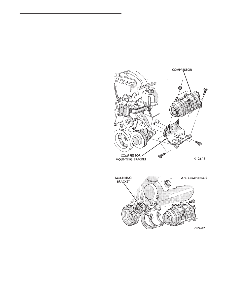
(4) Remove compressor attaching nuts and bolts
(Fig. 2 or 3).
(5) Remove compressor. If refrigerant lines were
not removed, lift compressor/clutch assembly and tie
it to a suitable component.
To install, reverse the preceding operation.
Fig. 2 A/C Compressor Removal and
Installation—3.3L Engines
Fig. 3 A/C Compressor Removal and
Installation—3.0 L Engine
Ä
HEATING AND AIR CONDITIONING
24 - 17
Нет комментариевНе стесняйтесь поделиться с нами вашим ценным мнением.
Текст