Chrysler Le Baron, Dodge Dynasty, Plymouth Acclaim. Manual — part 154

Fig. 38 Body Side Mouldings
23 - 26
AA-BODY
Ä

(3) Remove bolt holding seat belt to floor below
B-pillar.
(4) Lift B-pillar trim off door opening sill weather-
strips and push inward.
(5) Slide B-pillar trim downward as far as possible
and separate trim from B-pillar.
B-PILLAR TRIM PANEL INSTALLATION
Reverse the preceding operation.
QUARTER TRIM PANEL
REMOVAL (FIG. 39)
(1) Remove roof rail mouldings and scuff plates as
necessary.
(2) Remove shoulder harness turning loop cover.
Remove bolt holding turning loop to quarter panel.
(3) Remove rear seat cushion, back, and rear bol-
ster.
(4) Remove push-in fastener holding quarter trim
to roof rail.
(5) Remove screws holding quarter trim panel to
wheelhouse kickup.
(6) Pull trim panel forward and separate from ve-
hicle.
INSTALLATION
Reverse the preceding operation.
QUARTER EXTENSION TRIM PANEL
REMOVAL (FIG. 39)
(1) Remove rear seat cushion, back, and rear bol-
ster.
(2) Disengage clips holding expansion trim panel
to shelf panel.
(3) Separate trim panel from vehicle.
INSTALLATION
Reverse the preceding operation.
REAR SHELF TRIM PANEL
REMOVAL (FIG. 39)
(1) Remove one quarter trim panel.
(2) Remove center high mounted stop lamp cover.
Refer to Group 8L, Lamps for instructions.
(3) Disengage frog leg fasteners holding trim to
shelf panel and separate trim from vehicle.
INSTALLATION
Reverse the preceding operation.
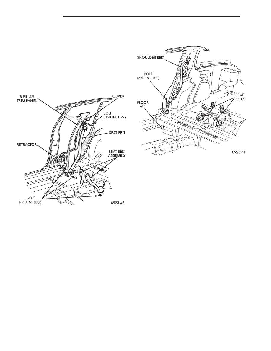
FRONT SEAT BELTS
OUTBOARD SHOULDER HARNESS/LAP BELT
REMOVAL (FIG. 40)
(1) Remove B-pillar trim panel.
(2) Remove bolt holding seat belt retractor to
B-pillar.
(3) Separate retractor from vehicle.
OUTBOARD SHOULDER HARNESS/LAP BELT
INSTALLATION
Reverse the preceding operation.
Fig. 39 Interior Mouldings, Panels, and Trim Covers
Ä
AA-BODY
23 - 27
INBOARD BUCKLE/CENTER OCCUPANT
BELTS REMOVAL (FIG. 40)
Vehicles equipped with front bucket seats with cen-
ter console do not have center occupant belts.
(1) Remove bolt holding inboard buckle/center oc-
cupant belt to floor.
(2) Disconnect seat belt sensor wire connector.
(3) Separate buckle/belt assembly from vehicle.
INBOARD BUCKLE/CENTER OCCUPANT BELT
INSTALLATION
Reverse the preceding operation.
REAR SEAT BELTS
OUTBOARD SHOULDER HARNESS/LAP BELT
REMOVAL (FIG. 41)
(1) Remove quarter trim panel.
(2) Remove bolt holding lap belt to floor at wheel-
house kickup.
(3) Remove bolt holding seat belt retractor to quar-
ter panel.
OUTBOARD SHOULDER HARNESS/LAP BELT
INSTALLATION
Reverse the preceding operation.
INBOARD BUCKLE/CENTER OCCUPANT
BELTS REMOVAL (FIG. 41)
(1) Remove rear seat cushion.
(2) Remove bolt holding inboard buckle/center oc-
cupant belt to floor.
(3) Separate buckle/belt assembly from vehicle.
INBOARD BUCKLE/CENTER OCCUPANT BELT
INSTALLATION
Reverse the preceding operation.
FRONT SEATS
REMOVAL (FIG. 42 OR 43)
(1) Position seat full forward.
(2) Remove screws holding rear track riser covers
and separate covers from tracks.
(3) On power seat track, remove outboard track
cover.
(4) On 50/50 seats, remove inboard seat belt at-
taching bolt from floor.
(5) Remove nuts holding seat track to floor.
(6) Position seat full rearward.
(7) On power seat track, remove door sill scuff
plate and disconnect wire connector.
(8) Remove bolts holding seat track to cross mem-
ber.
(9) Remove seat from vehicle.
INSTALLATION
Reverse the preceding operation.
REAR SEATS
REAR SEAT CUSHION REMOVAL
(1) Remove bolts holding cushion to floor.
(2) Push center occupant seat belts through open-
ings in cushion.
(3) Remove cushion from vehicle.
REAR SEAT CUSHION INSTALLATION
Reverse the preceding operation.
Fig. 40 Front Seat Belts
Fig. 41 Rear Seat Belts
23 - 28
AA-BODY
Ä
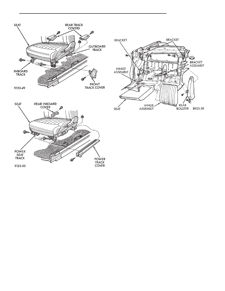
REAR SEAT BACK REMOVAL (FIG. 44)
(1) Hinge seat back forward and disengage push-in
fasteners holding carpet backing to trunk floor.
(2) Remove bolts holding outboard hinge pivot
bracket to seat back.
(3) Pull seat back outward to disengage inboard
pivot and separate from vehicle.
REAR SEAT BACK INSTALLATION
Reverse the preceding operation.
SEAT BACK BOLSTER CUSHION REMOVAL
(FIG. 44)
(1) Remove rear seat cushion and back as neces-
sary.
(2) Remove bolts holding outboard back bolster to
quarter panel.
(3) Lift bolster upward to disengage hook retainer
on back of bolster and separate from vehicle.
SEAT BACK BOLSTER CUSHION
INSTALLATION
Reverse the preceding operation
FRONT CENTER CONSOLE
REMOVAL (FIG. 45)
(1) Position front seats full forward.
(2) Remove access hole plugs on sides of center
arm rest riser and remove bolts holding riser to floor
bracket.
(3) Remove coin holder and remove screws holding
arm rest riser to front console.
(4) Position front seats full rearward.
(5) Remove radio bezel from instrument panel. Re-
fer to Group 8E, Instrument Panel. Remove screws
holding console to instrument panel.
(6) Remove screws holding console to lower instru-
ment panel rail.
(7) Remove screws and disengage hook and loop
fastener holding carpet panels to sides of console and
separate panels from console.
(8) Remove screws holding console to forward floor
mounting bracket.
(9) Remove set screw holding gear selector knob to
shift lever and pull knob from shifter on vehicles
with automatic transaxle.
(10) Lift forward edge of PRNDL cover and sepa-
rate cover from console on vehicles with automatic
transaxle.
(11) Lift gear shift boot adapter from console and
push adapter through opening in console on vehicles
with manual transaxle.
(12) Separate console from floor and remove from
vehicle.
Fig. 42 Manual Front Seat
Fig. 43 Power Front Seat
Fig. 44 Rear Seat Cushion and Back
Ä
AA-BODY
23 - 29
Нет комментариевНе стесняйтесь поделиться с нами вашим ценным мнением.
Текст