Chrysler Le Baron, Dodge Dynasty, Plymouth Acclaim. Manual — part 152
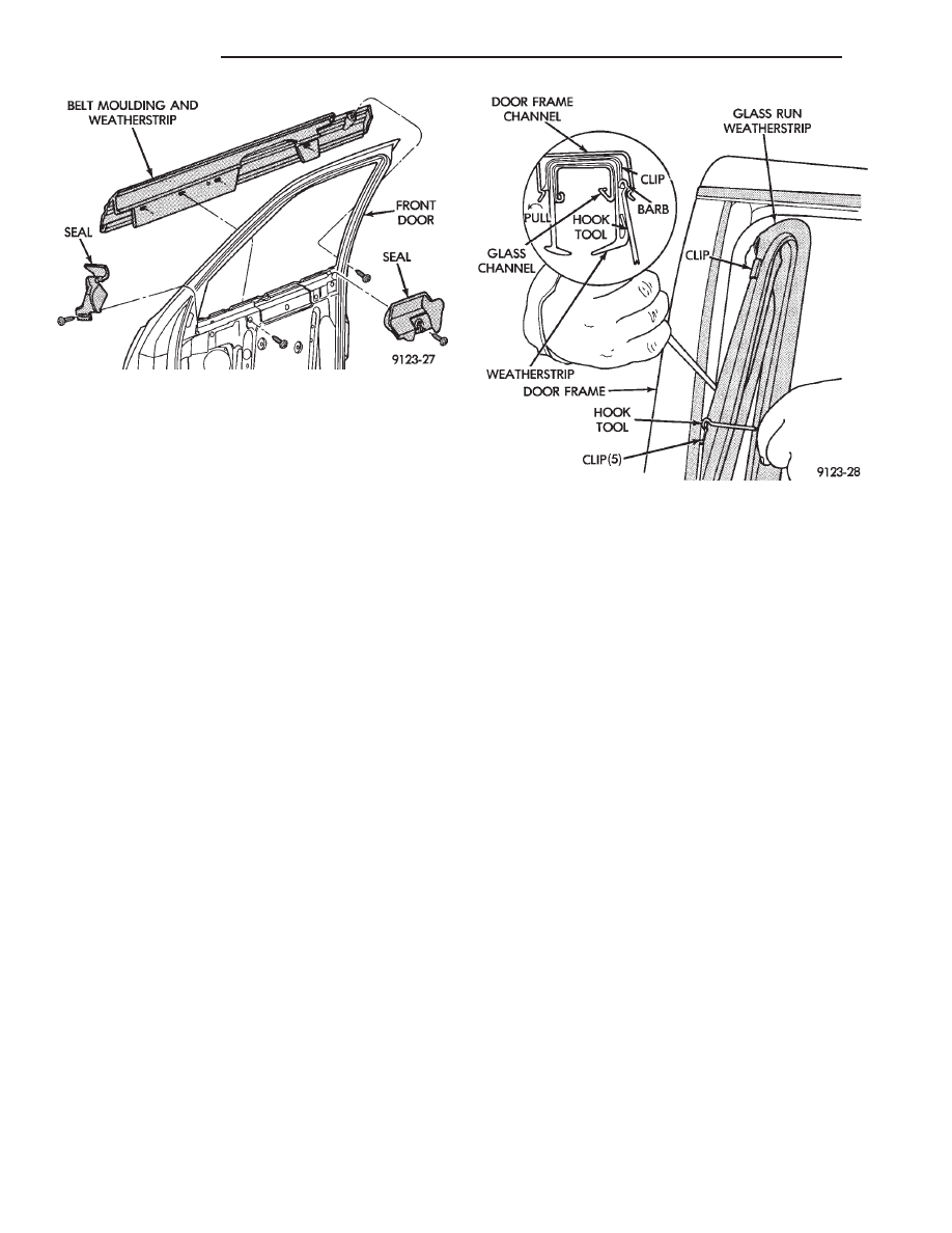
FRONT DOOR GLASS CHANNEL AND RUN
WEATHERSTRIP
GLASS CHANNEL AND RUN WEATHERSTRIP
REMOVAL (FIG. 19)
(1) Remove door belt moulding and weatherstrip
assembly.
(2) Remove front and rear door glass opening cor-
ner seals (Fig. 18)
(3) Pull door glass run weatherstrip from forward
lower channel and upper door frame back to rear up-
per corner of door frame.
(4) Separate weatherstrip from top of rear door
frame down to first clip. Using a suitable hook tool,
disengage clip barb from door frame channel. Pull
weatherstrip outward to disengage clip. Repeat this
procedure at each clip down the rear channel.
(5) Separate glass channel and run weatherstrip
from door.
GLASS CHANNEL AND RUN WEATHERSTRIP
INSTALLATION
(1) Insert glass run weatherstrip into top of glass
opening upper channel. Align molded corners of
weatherstrip to corners of glass opening.
(2) Push weatherstrip and glass run channel into
upper rear glass opening channel. Seat the top re-
taining clip by placing a fiber trim stick (C-4755)
over the clip attaching rivet inside the glass run
channel and push or tap firmly inward until clip
seats. Verify the alignment of the weatherstrip in
the top rear corner. Repeat this procedure on each
clip going down the run.
(3) Install glass opening corner seals.
(4) Install door belt moulding and weatherstrip as-
sembly.
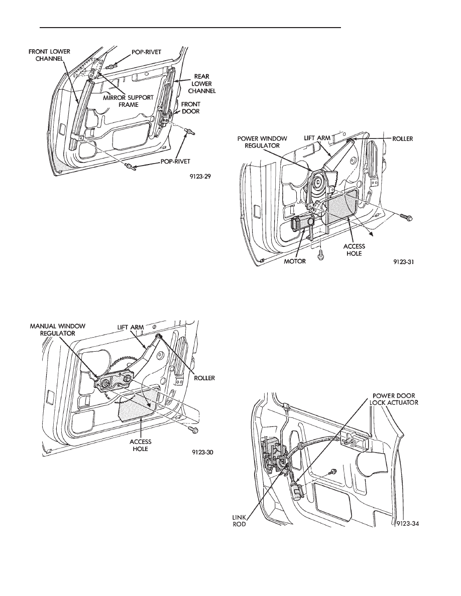
FRONT DOOR GLASS RUN LOWER CHANNEL
FRONT OR REAR LOWER CHANNEL REMOVAL
(FIG. 20)
(1) Remove door glass channel and run weather-
strip as necessary to gain access to lower channels
and attaching rivets.
(2) Drift punch rivet center expansion pins from
each pop-rivet fastener holding channel to door panel
or mirror support frame.
(3) Drill pop-rivet fasteners out of door panel or
mirror support frame and separate front or rear
channel from door.
FRONT OR REAR LOWER CHANNEL
INSTALLATION
(1) Install lower channel into at design location.
(2) Install pop-rivets using a suitable pop-rivet
gun.
(3) Install Glass channel and run weatherstrip.
(4) Install belt moulding and weatherstrip assem-
bly.
(5) Install door glass.
(6) Install window opening lower corner seals.
(7) Install door water shield silencer pad and trim
panel.
FRONT DOOR WINDOW REGULATOR/MANUAL
MANUAL WINDOW REGULATOR REMOVAL
(FIG. 21)
(1) Remove trim panel, silencer pad, and water
shield.
Fig. 18 Front Door Belt Moulding and Weatherstrip
Fig. 19 Front Door Glass Channel and Run
Weatherstrip
23 - 18
AA-BODY
Ä
(2) Raise glass to 25 mm (1 in.) from full up posi-
tion. Using suitable tape, secure door glass to upper
window frame.
(3) Remove bolts holding window regulator to in-
ner door panel.
(4) Slide roller from window lift channel. Rotate
regulator
to bring lift arm through access hole first.
(5) Remove regulator assembly from door.
MANUAL WINDOW REGULATOR
INSTALLATION
Reverse the preceding operation.
FRONT DOOR WINDOW REGULATOR/POWER
POWER WINDOW REGULATOR REMOVAL
(FIG. 22)
(1) Remove trim panel and water shield and con-
nect window switch to wire connector.
(2) Raise glass to 25 mm (1 in.) from full up posi-
tion. Using suitable tape, secure door glass to upper
window frame.
(3) Disconnect battery negative cable.
(4) Remove bolts holding window regulator to in-
ner door panel.
(5) Slide roller from window lift channel. Rotate
regulator
to bring lift arm through access hole first.
(6) Remove regulator assembly from door.
POWER WINDOW REGULATOR INSTALLATION
Reverse the preceding operation.
FRONT POWER DOOR LOCK ACTUATOR
REMOVAL (FIG. 23)
(1) Remove trim panel, silencer pad, and water
shield.
(2) Disconnect link rod from door latch.
(3) Remove bolts holding power door lock actuator
to inner door panel and separate actuator from door.
INSTALLATION
Reverse the preceding operation.
Fig. 20 Front Door Lower Channels
Fig. 21 Front Door Window Regulator—Manual
Fig. 22 Front Door Window Regulator—Power
Fig. 23 Front Power Door Lock Actuator
Ä
AA-BODY
23 - 19
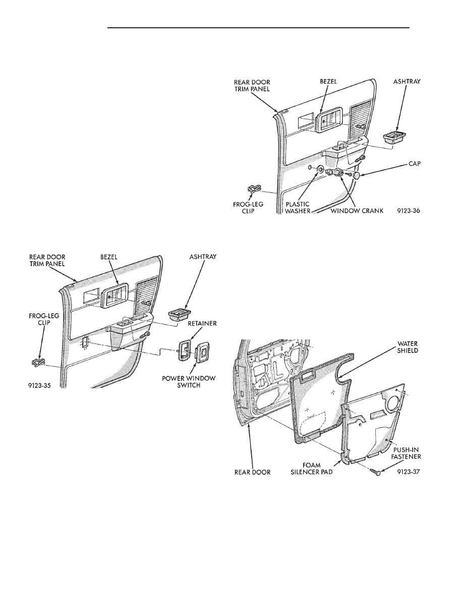
REAR DOOR TRIM PANEL
DOOR TRIM PANEL WITH POWER WINDOWS
REMOVAL (FIG. 24)
(1) Move glass to down position.
(2) Disconnect battery negative cable.
(3) Remove screw holding latch release handle be-
zel to door. Slide bezel forward and separate from
door trim.
(4) Remove ash tray. Remove screw holding trim
panel to door from ash tray opening.
(5) Pry power window switch from retainer in door
trim and disconnect wire connector.
(6) Using a suitable trim clip tool, disengage frog
leg clips at the ends and bottom of trim panel. After
all trim clips are loose, push inward at the top of the
trim panel and lift upward to disengage barb fasten-
ers at top of panel. Separate trim from door.
DOOR TRIM PANEL WITH POWER WINDOWS
INSTALLATION
Reverse the preceding operation.
DOOR TRIM PANEL WITH MANUAL WINDOWS
REMOVAL (FIG. 25)
(1) Move glass to down position.
(2) Remove screw holding latch release handle be-
zel to door. Slide bezel forward and separate from
door trim.
(3) Remove ash tray. Remove screw holding trim
panel to door from ash tray opening.
(4) Pry window crank cap from crank. Remove
screw holding crane to regulator and separate from
door
(6) Using a suitable trim clip tool, disengage frog
leg clips at the ends and bottom of trim panel. After
all trim clips are loose, push inward at the top of the
trim panel and lift upward to disengage barb fasten-
ers at top of panel. Separate trim from door.
DOOR TRIM PANEL WITH MANUAL WINDOWS
INSTALLATION
Reverse the preceding operation.
REAR DOOR SILENCER AND WATER SHIELD
REMOVAL (FIG. 26)
(1) Remove door trim panel.
(2) Remove push-in fasteners holding silencer pad
to door inner panel and separate silencer from door.
(3) Pull water shield from adhesive around perim-
eter of door inner panel.
INSTALLATION
Reverse the preceding operation.
REAR DOOR AND HINGE
The rear door hinge is welded to the door and
bolted to the B-pillar. The door half of the hinge piv-
ots on a removable hinge pin. The hinge pin is
driven in from the bottom on the top hinge and from
the top on the bottom hinge. All adjustments to the
hinge are performed on the hinge pillar half of the
Fig. 24 Rear Door Trim Panel with Power Windows
Fig. 25 Rear Door Trim Panel with Manual Window
Fig. 26 Rear Door Silencer and Water Shield
23 - 20
AA-BODY
Ä

hinge. If the welded half of the hinge must be bent to
align door, consult an authorized body repair facility.
REAR DOOR REMOVAL (FIG. 27)
(1) Remove B-pillar trim panel and disconnect all
wire connectors leading to door. Push wire harness
through access hole in B-pillar into hinge opening.
(2) Support door on a suitable lifting device.
(3) Drive bottom hinge pin upward and remove pin
from hinge.
(4) Drive top hinge pin downward and remove pin
from hinge.
(5) Separate door from vehicle.
REAR DOOR INSTALLATION
Reverse the preceding operation. The door should
not require re-alignment. If door does need align-
ment, refer to Rear Door Hinge Installation para-
graph in this section.
REAR DOOR HINGE REMOVAL (FIG. 27)
(1) To remove upper hinge bolted half, remove
B-pillar trim panel. To remove lower hinge bolted
half it is not necessary to remove B-pillar trim.
(2) Support rear door on a suitable lifting device.
(3) Drive out hinge pin on the effected hinge.
(4) Remove bolts holding hinge to B-pillar and sep-
arate hinge form vehicle.
REAR DOOR HINGE INSTALLATION
Reverse the preceding operation. Align door to
achieve 6 mm (0.240 in.) gap to all surrounding pan-
els and flush across gaps.
OUTSIDE REAR DOOR LATCH RELEASE HANDLE
REMOVAL (FIG. 28)
(1) Remove door trim panel, silencer pad, and wa-
ter shield.
(2) Raise door glass to full up position.
(3) Remove rear door speaker, if equipped.
(4) Disconnect latch release rod from door latch as-
sembly.
(5) Remove nuts holding outside door latch handle
to retainer bracket and separate bracket from door.
(6) Separate latch handle from door panel.
INSTALLATION
Reverse the preceding operation.
REAR DOOR LATCH
REMOVAL (FIG. 29)
(1) Remove door trim panel, silencer pad and wa-
ter shield.
(2) Raise door glass to full up position.
(3) Remove door speaker, if equipped.
(4) Disconnect all actuator rods from door latch as-
sembly.
(5) Remove screws holding door latch assembly to
inner door rear panel and separate from door.
INSTALLATION
Reverse the preceding operation.
Fig. 27 Rear Door Assembly
Fig. 28 Outside Rear Door Latch Release Handle
Fig. 29 Rear Door Latch Assembly
Ä
AA-BODY
23 - 21
Нет комментариевНе стесняйтесь поделиться с нами вашим ценным мнением.
Текст