Chrysler Le Baron, Dodge Dynasty, Plymouth Acclaim. Manual — part 276

NIPPONDENSO STARTER GEAR AND CLUTCH
REMOVAL AND INSTALLATION
(1) Remove the two gear housing attaching screws
and separate the gear housing from the solenoid
housing (Fig. 10). The pinion gear, pinion gear bear-
ing, and drive gear will be loose between the solenoid
housing and gear housing (Fig. 11). When reinstall-
ing pinion gear and bearing, wipe with a clean rag
and coat with lightweight high temperature wheel
bearing grease. Place the lubricated bearing and
gear over the bearing shaft in the gear housing (Fig.
12).
(2) Remove the starter gear and clutch assembly
from the solenoid housing (Fig. 13).
(3) For assemble, reverse above procedures.
BOSCH STARTER SOLENOID REPLACEMENT
(1) Remove field terminal nut (Fig. 14).
(2) Remove field terminal (Fig. 15).
(3) Remove field washer (Fig. 16).
(4) Remove three solenoid mounting screws (Fig.
17).
(5) Remove the solenoid from the starter assembly.
(6) For installation, reverse above procedures.
Fig. 8 Remove/Install Starter—Bosch—Typical
Fig. 9 Remove/Install
Starter—Nippondenso—Typical
Fig. 10 Remove or Install Gear Housing
Fig. 11 Remove or Install Drive and Pinion Gears
Fig. 12 Lubricate and Install Pinion Gear Bearing
8B - 6
BATTERY/STARTER/GENERATOR SERVICE
Ä

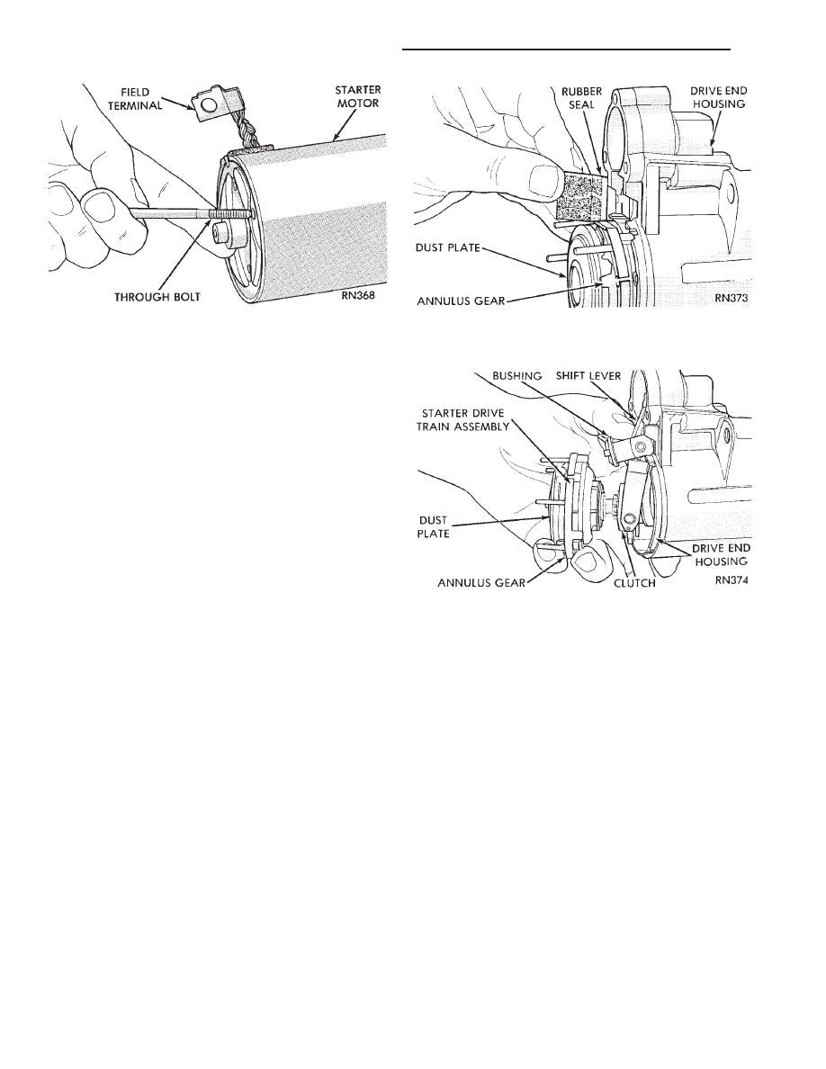
BOSCH STARTER GEAR AND CLUTCH
REPLACEMENT
(1) Remove solenoid assembly (Fig. 18).
(2) Remove the two through-bolts securing the
starter drive end housing to the motor housing (Fig.
19) and separate housings.
(3) Remove rubber seal (Fig. 20).
(4) Pull the gear and clutch assembly from the
drive end housing (Fig. 21).
(5) For installation, reverse above procedures.
STARTER INTERLOCK SWITCH: CLUTCH PEDAL
MOUNTED/MANUAL TRANSMISSION ONLY
For electrical diagnostics, refer to Group 8A, Bat-
tery/Starting/Charging Systems Diagnostics, Starter
relays.
Fig. 13 Gear and Clutch Assembly
Fig. 14 Field Terminal Nut
Fig. 15 Field Coil Terminal
Fig. 16 Field Terminal Washer
Fig. 17 Solenoid Mounting Screws
Fig. 18 Solenoid
Ä
BATTERY/STARTER/GENERATOR SERVICE
8B - 7
For replacement and adjustment of this switch, re-
fer to Group 6, Manual Transaxle Clutch, Manual
Transaxle Starter Interlock Switch.
NEUTRAL STARTER AND BACK-UP SWITCH
For
electrical
diagnostics
when
checking
the
starter circuits, refer to Group 8A, Battery/Starting/
Charging Systems Diagnostics, Starter Relays.
For removal and installation of neutral switch, re-
fer to Group 21, Transaxle Neutral Starter and
Back-up Switch Replacement.
Fig. 19 Through-Bolt
Fig. 20 Rubber Seal
Fig. 21 Starter Drive Gear Train
8B - 8
BATTERY/STARTER/GENERATOR SERVICE
Ä

GENERATOR
INDEX
page
page
General Information
. . . . . . . . . . . . . . . . . . . . . . . . 9
Generator Replacement—2.2L Turbo Engine
(With 16 Valve Cylinder Head)
. . . . . . . . . . . . . 10
Generator Replacement—2.2L/2.5L Engine
. . . . . . 9
Generator Replacement—3.0L Engine
. . . . . . . . . 10
Generator Replacement—3.3L/3.8L Engine
. . . . . 11
GENERAL INFORMATION
This section will cover generator removal and instal-
lation only. Information covering generator on-vehicle
testing and diagnosis can be found in Group 8A,
Battery/Starting/Charging Systems Diagnostics. To
identify the generator, refer to the Generator Specifi-
cation chart at the rear of this section.
These generators are not intended to be disas-
sembled for service. It must be replaced as an
assembly.
GENERATOR REPLACEMENT—2.2L/2.5L ENGINE
Removal and repositioning of A/C compressor (with-
out disconnecting refrigerant lines) is necessary on
some models to gain access to generator.
(1) Disconnect battery negative cable (Fig. 1).
(2) If Equipped With Air Conditioning:
(a) Remove the A/C drive belt. Refer to Group 7,
Cooling System.
(b) Remove the four bolts retaining the A/C com-
pressor to the mounting bracket (Fig. 2).
(c) Without disconnecting the A/C refrigerant
lines, position the A/C compressor to allow generator
removal.
WARNING: THE A/C REFRIGERANT SYSTEM IS UN-
DER PRESSURE EVEN WHEN THE ENGINE IS OFF.
REFER TO THE SAFETY PRECAUTIONS AND WARN-
INGS SECTION IN HEATING AND A/C, GROUP 24,
BEFORE PERFORMING ANY SERVICE OPERATION.
(3) Remove the generator drive belt. Refer to Group
7, Cooling System.
(4) Remove the two generator mounting bolts (Fig.
3) and position the generator to gain access to all the
wire connectors. If equipped with:
• BOSCH GENERATOR: Remove B+ terminal nut,
field terminal nuts, and ground harness hold down
nuts (Fig. 4). Remove wire connector assembly.
• NIPPONDENSO GENERATOR: Remove nuts
from field terminals, ground terminal, wire harness
Fig. 1 Remove Battery Negative (-) Cable
Fig. 2 A/C Compressor Replacement—2.2 L/2.5 L
Engine
Fig. 3 Remove/Install Generator
Ä
BATTERY/STARTER/GENERATOR SERVICE
8B - 9
Нет комментариевНе стесняйтесь поделиться с нами вашим ценным мнением.
Текст