Chrysler Le Baron, Dodge Dynasty, Plymouth Acclaim. Manual — part 277
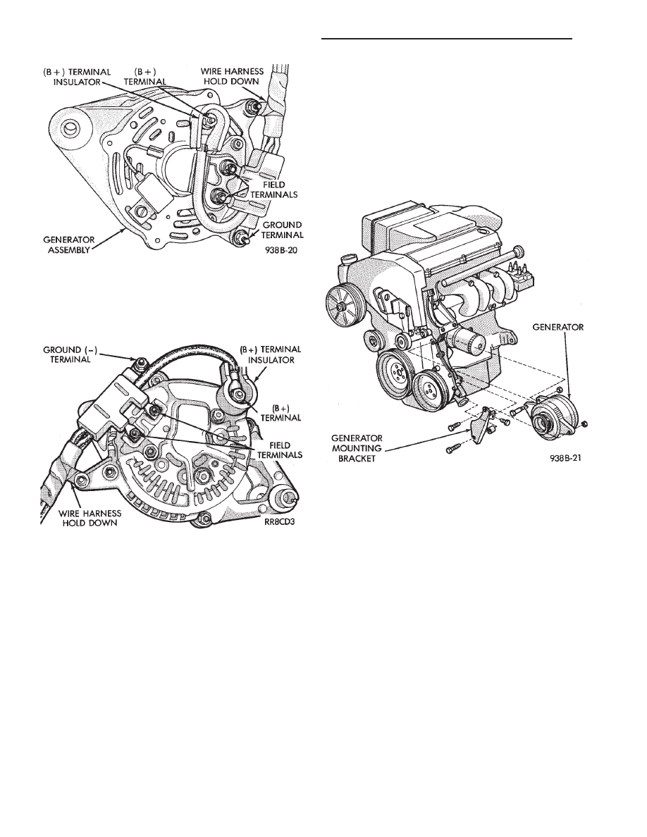
and B+ terminal (Fig. 5). B+ terminal nut must be
removed last to prevent damage to terminal insula-
tor.
(5) Remove the generator from the vehicle.
(6) For
installation,
reverse
above
procedures.
Tighten all fasteners to the proper torque. Refer to
the Torque Specifications chart at the rear of this
group.
GENERATOR REPLACEMENT—2.2L TURBO
ENGINE (WITH 16 VALVE CYLINDER HEAD)
(1) Disconnect battery NEGATIVE cable (Fig. 1).
(2) Remove generator/air conditioning drive belt.
Refer to Group 7, Cooling System.
(3) Remove the bolts retaining the A/C compressor
to the mounting bracket.
(4) Without
disconnecting
the
A/C
refrigerant
lines, position the A/C compressor to allow generator
removal.
WARNING: THE A/C REFRIGERANT SYSTEM IS UN-
DER PRESSURE EVEN WHEN THE ENGINE IS OFF.
REFER
TO
THE
SAFETY
PRECAUTIONS
AND
WARNINGS
SECTION
IN
HEATING
AND
A/C,
GROUP 24, BEFORE PERFORMING ANY SERVICE
OPERATION.
(5) Remove the generator mounting bracket bolts
and separate generator from mounting bracket (Fig.
6).
(6) Remove the B+ terminal nut, field terminal
nuts, and ground/wire harness hold-down nuts. Re-
move wire connectors.
(7) Remove the generator from the vehicle.
(8) For
installation,
reverse
above
procedures.
Tighten all fasteners to the proper torque. Refer to
the Torque Specifications chart at the rear of this
group.
GENERATOR REPLACEMENT—3.0L ENGINE
(1) Disconnect battery negative cable (Fig. 1).
(2) Remove generator drive belt. Refer to Group 7,
Cooling System.
(3) Remove the generator mounting bolts and sep-
arate the generator from the mounting bracket (Fig.
7).
(4) Remove the B+ terminal nut, field terminal
nuts, and ground/wire harness hold-down nuts. Re-
move wire connectors.
(5) Remove the generator from the vehicle.
Fig. 4 Remove or Install Wire Connector
Assembly—Bosch Generator
Fig. 5 Remove or Install Wire Connector
Assembly—Nippondenso Generator
Fig. 6 Generator Mounting—2.2 L Turbo Engine
With 16 Valve Cylinder Head
8B - 10
BATTERY/STARTER/GENERATOR SERVICE
Ä
(6) For
installation,
reverse
above
procedure.
Tighten all fasteners to the proper torque. Refer to
the Torque Specifications chart at the rear of this
group.
GENERATOR REPLACEMENT—3.3L/3.8L ENGINE
(1) Disconnect battery negative cable (Fig. 1).
(2) Remove generator drive belt. Refer to Group 7,
Cooling System.
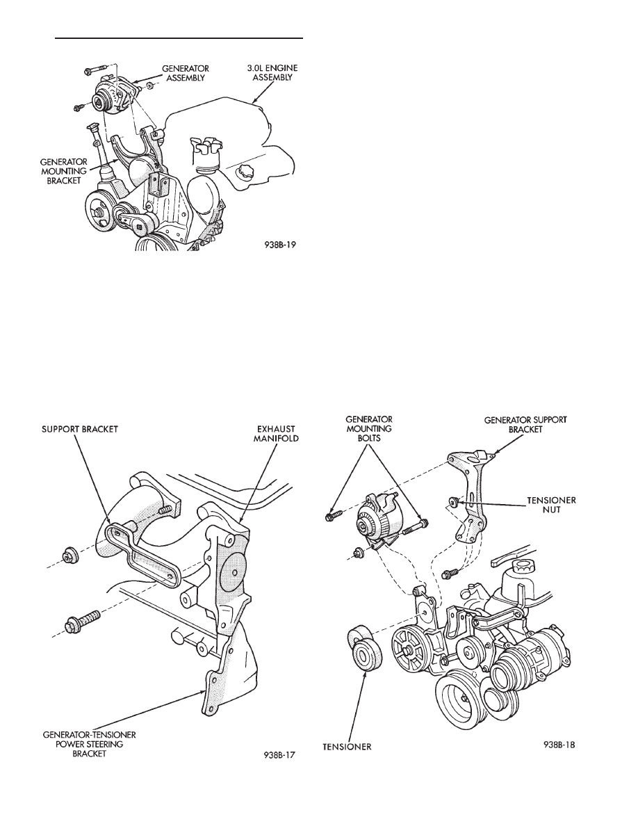
(3) Loosen, but do not remove the nut on the sup-
port bracket at exhaust manifold (Fig. 8).
(4) Remove the generator tensioner power steering
bracket bolt.
(5) Remove the tensioner stud nut and the ten-
sioner (Fig. 9).
(6) Remove the generator mounting bolts (Fig. 9).
(7) Remove the power steering reservoir from the
generator mounting bracket.
(8) Remove the three generator support bracket
bolts (Fig. 8).
(9) Remove intake plenum to generator mounting
bracket bolt.
(10) Remove generator support bracket (Fig. 9).
(11) Position the generator to gain access to wiring
and remove wiring from generator.
(12) Remove generator.
(13) For installation, reverse above procedures.
Tighten all fasteners to the proper torque. Refer to
the Torque Specifications chart at the rear of this
group.
Fig. 7 Remove or Install Generator Mounting
Bolts—3.0L Engine
Fig. 8 Support Bracket
Fig. 9 Generator/Generator Support Bracket—3.3L/
3.8L Engine
Ä
BATTERY/STARTER/GENERATOR SERVICE
8B - 11

SPECIFICATIONS
STARTER/BATTERY
GENERATOR AMPERAGE/IDENTIFICATION NUMBERS
8B - 12
BATTERY/STARTER/GENERATOR SERVICE
Ä
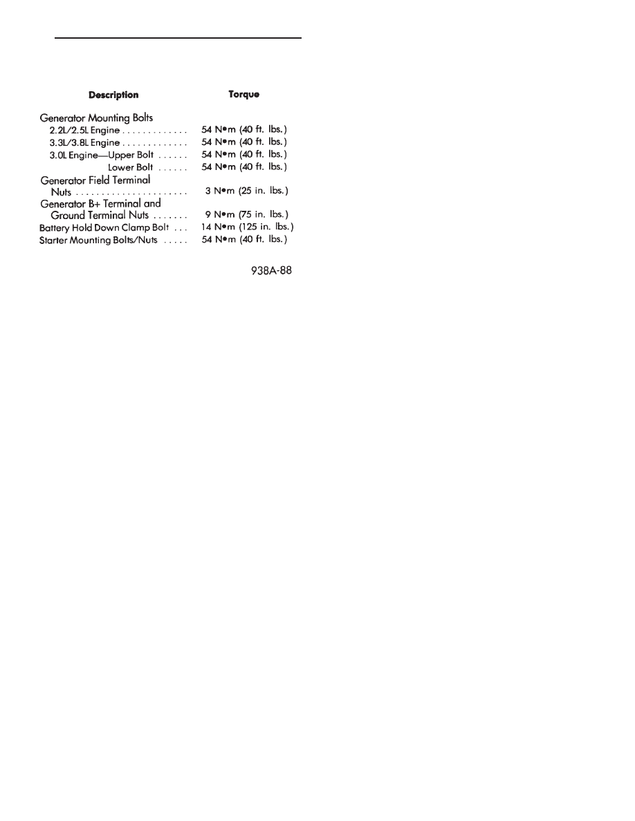
TORQUE SPECIFICATIONS
Ä
BATTERY/STARTER/GENERATOR SERVICE
8B - 13
Нет комментариевНе стесняйтесь поделиться с нами вашим ценным мнением.
Текст