Chrysler Le Baron, Dodge Dynasty, Plymouth Acclaim. Manual — part 583
(c) Remove LEFT insulator through bolt from in-
side wheelhouse or insulator bracket to transmis-
sion screws.
(22) Remove engine.
INSTALLATION
(1) Attach hoist and lower engine into engine com-
partment.
(2) Align engine mounts and install but do not
tighten until all mounting bolts have been installed.
Tighten bolts to torque specified in (Fig. 2).
(3) Install transmission case to cylinder block,
tighten bolts to 102 N
Im (75 ft. lbs.) torque.
(4) Remove engine hoist and transmission holding
fixture.
(5) Remove C clamp from torque converter hous-
ing. Align flex plate to torque converter and install
mounting screws. Tighten to 75 N
Im (55 ft. lbs.)
(6) Install transmission inspection cover.
(7) Connect exhaust system at manifold.
(8) Install starter.
(9) Install power steering pump and air condition-
ing compressor. For belt installation Refer to Acces-
sory Belt Drive in Cooling System Group 7.
(10) Lower vehicle and connect all vacuum lines.
(11) Connect all electrical connections including
ground strap.
(12) Connect fuel lines and accelerator cable.
(13) Install radiator and fan assembly. Connect fan
motor electrical lead. Install radiator hoses. Fill cool-
ing system. Refer to Cooling System Group 7 for fill-
ing procedure.
(14) Fill engine crankcase with proper oil to cor-
rect level.
(15) Install hood.
(16) Connect battery.
(17) Start engine and run until operating temper-
ature is reached.
(18) Adjust transmission or linkage if necessary.
ACCESSORY DRIVE BELT SERVICE
REMOVAL
(1) Loosen Adjusting Lock Nut (Fig. 6).
(2) Turn adjusting jack screw counterclockwise to
reduce belt tension. Remove belt.
(3) Inspect drive belt for wear and damage (Fig. 5).
(4) Installation: Adjust belt tension to 5/16 deflec-
tion between pulleys (Fig. 6).
(5) Install breaker bar into 1/2 square opening in
tensioner.
(6) Rotate tensioner clockwise to remove and in-
stall belt (Fig. 7).
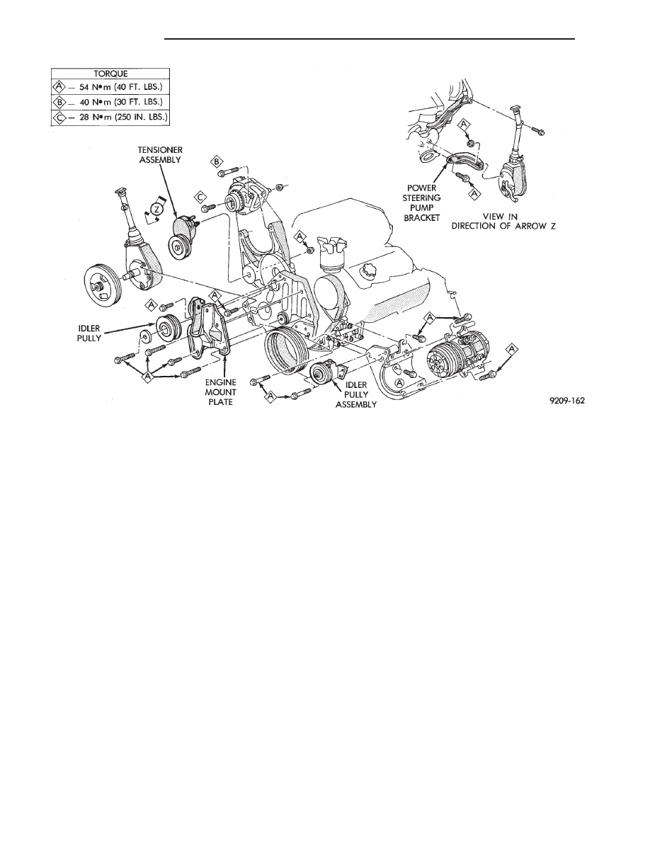
Fig. 4 Accessories Mounting Brackets
9 - 70
3.0L ENGINE
Ä

ENGINE MOUNT BRACKET
REMOVAL
(1) Remove air conditioning compressor to mount-
ing bracket screws and lay compressor aside (Fig. 4).
(2) Remove screws attaching air conditioning com-
pressor mounting bracket and adjustable drive belt
tensioner from block and engine mounting bracket.
Remove both assemblies.
(3) Remove steering pump/generator belt tensioner
mounting bolt and remove automatic belt tensioner.
(4) Remove two steering pump to engine mounting
bracket screws and one rear support lock nut.
(5) Lay power steering pump aside.
(6) Raise vehicle and remove right inner splash
shield (Fig. 8).
(7) Remove crankshaft drive pulleys and torsional
damper (Fig. 9).
(8) Lower vehicle and place a jack under engine.
Fig. 5 Drive Belt Inspection
Fig. 6 Air Conditioning Belt
Fig. 7 Generator/Power Steering Belt
Fig. 8 Right Inner Splash Shield—Typical
Fig. 9 Crankshaft Drive Pulleys
Ä
3.0L ENGINE
9 - 71
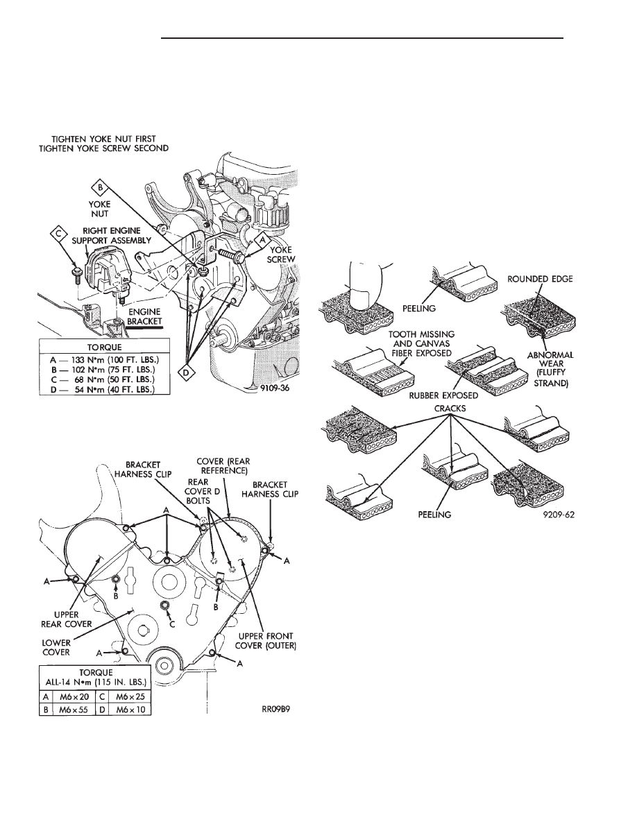
(9) Mark support assembly to engine bracket if as-
sembly is to be used again. Separate engine mount
insulator from engine mount bracket (Fig. 10). Raise
engine slightly.
(10) Remove engine mount bracket (Fig. 10).
(11) Remove timing belt covers (Fig. 11).
TIMING BELT INSPECTION—IN VEHICLE
(1) Remove the upper front outer timing belt cover
by loosening the three attaching bolts. (Fig. 11).
(2) Inspect both sides of the timing belt drive &
back. Replace belt if any of the following conditions
exist.
• Hardening of back rubber back side is glossy with-
out resilience and leaves no indent when pressed
with fingernail.
• Cracks on rubber back.
• Cracks or peeling of canvas.
• Cracks on rib root.
• Cracks on belt sides.
• Missing teeth.
• Abnormal wear of belt sides. The sides are normal
if they are sharp as if cut by a knife (Fig. 12).
(3) If none of the above conditions are seen on the
belt, the belt cover can be reinstalled.
TIMING BELT SERVICE
REMOVAL
(1) Mark belt running direction for installation
(Fig. 14).
(2) Loosen timing belt tensioner bolt (Fig. 16) and
remove timing belt.
(3) Remove crankshaft sprocket flange shield (Fig.
9).
CAMSHAFT SPROCKETS
REMOVAL
(1) Hold camshaft sprocket with Spanner Tool
MB990775 loosen and remove bolt and washer (Fig.
15).
(2) Remove camshaft sprocket from camshaft.
Fig. 10 Right Engine Mount and Engine Mount
Bracket
Fig. 11 Timing Belt Covers
Fig. 12 Timing Belt Inspection
9 - 72
3.0L ENGINE
Ä
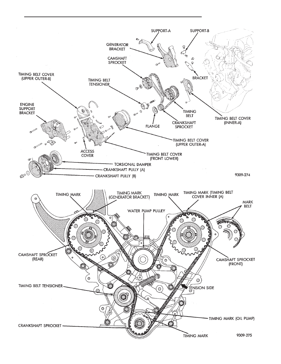
Fig. 13 Timing Belt System
Fig. 14 Timing Belt Engine Sprocket Timing
Ä
3.0L ENGINE
9 - 73
Нет комментариевНе стесняйтесь поделиться с нами вашим ценным мнением.
Текст