Chrysler Le Baron, Dodge Dynasty, Plymouth Acclaim. Manual — part 584

INSTALLATION
(1) Place camshaft sprocket on camshaft.
(2) Install bolt and washer to camshaft. Using
Spanner Tool MB990775 hold camshaft sprocket and
torque bolt to 95 N
Im (70 ft. lbs.) (Fig. 15).
TIMING BELT TENSIONER
(1) Install timing belt tensioner and tensioner
spring.
(2) Hook spring upper end to water pump pin and
lower end to tensioner bracket with hook out (Fig. 16).
(3) Turn timing belt tensioner counter-clockwise full
travel in adjustment slot and tighten bolt to tempo-
rarily hold this position (Fig. 17).
INSTALLATION—TIMING BELT
(1) Install timing belt on crankshaft sprocket first
and while keeping belt tight on tension side (Fig. 14)
install belt on the front (radiator side) camshaft
sprocket.
(2) Then, install on the water pump pulley and on
the rear camshaft sprocket and finally on the timing
belt tensioner.
(3) Apply rotating force to the front camshaft
sprocket in opposite direction to tension the belt ten-
sion side, check that all timing marks are lined up (Fig.
14).
(4) Install crankshaft sprocket flange (Fig. 12).
(5) Loosen tensioner bolt and allow spring to tension
timing belt.
(6) Turn crankshaft two full turns in clockwise di-
rection. Turn smoothly and in clockwise direction
ONLY.
(7) Again line up the timing marks on the sprockets
and tighten the timing belt tensioner locking bolt to 25
N
Im (250 in. lbs.) torque.
(8) Reassembly belt covers, engine bracket, insula-
tor, crankshaft pulleys, accessories and accessory drive
belts in reverse order.
Fig. 15 Camshaft Sprockets
Fig. 16 Timing Belt Tensioner
Fig. 17 Positioning Belt Tensioner
9 - 74
3.0L ENGINE
Ä
CYLINDER HEAD AND CAMSHAFT SERVICE
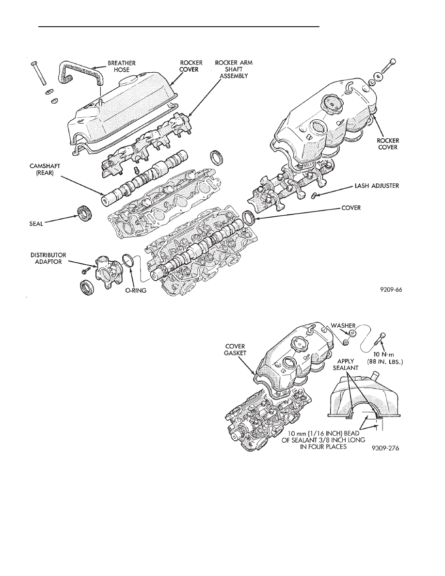
CYLINDER HEAD COVER
REMOVE
(1) Remove air cleaner assembly.
(2) Disconnect battery and relocate spark plug
wires.
(3) Remove vacuum connections.
(4) Remove rocker cover screws and remove cover
(Fig. 2).
INSTALL
(1) Clean cylinder head and cover mating surfaces.
Install new gasket.
(2) See (Fig. 2) and apply sealant such as Mopar
Silicone Rubber Adhesive Sealant to cover ends.
(3) Install cover and tighten cover bolt washer and
gasket assembly to 10 N
Im (88 in. lbs.).
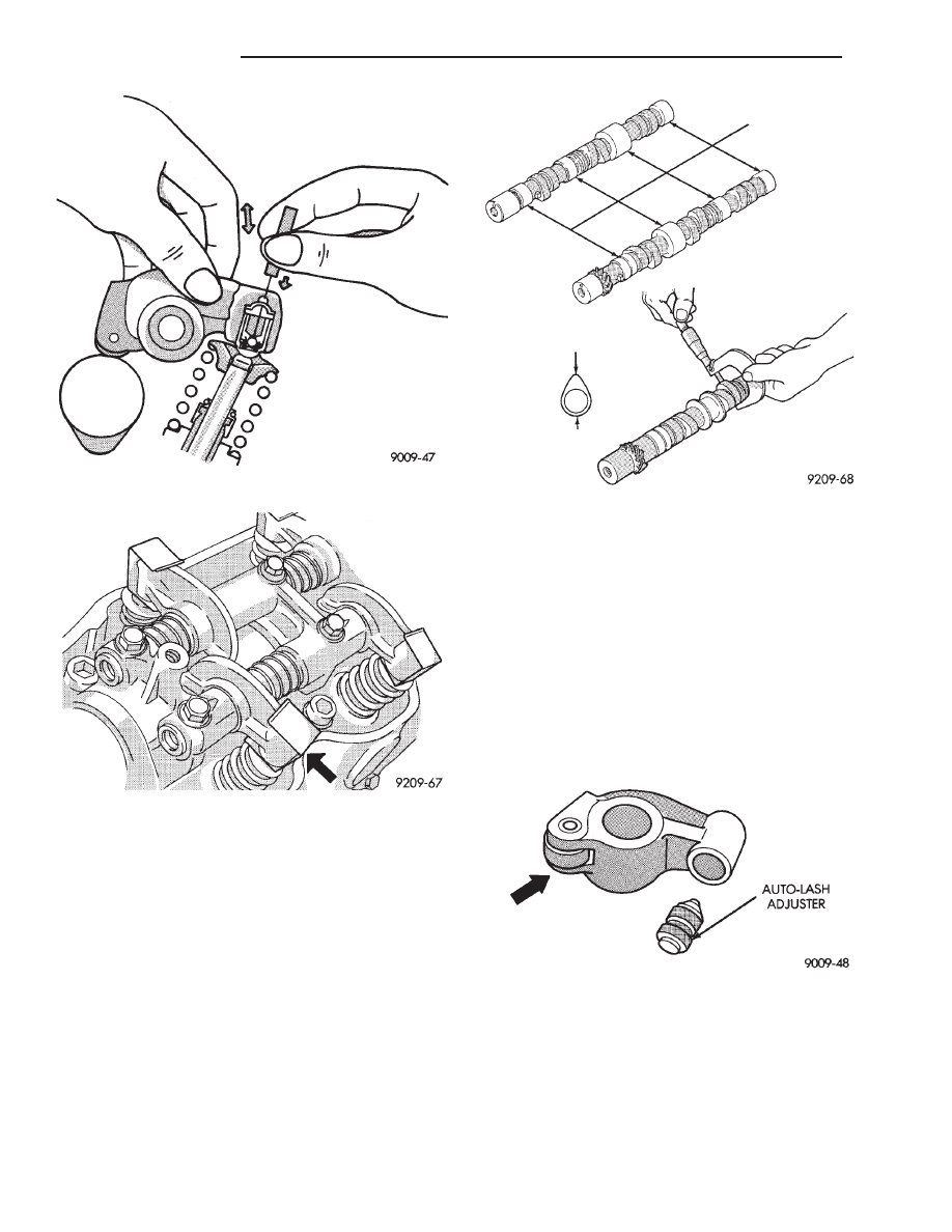
AUTO LASH ADJUSTER
The automatic lash adjusters are precision units in-
stalled in machined openings in the valve actuating
ends of the rocker arms. Do not disassemble the auto
lash adjuster.
FUNCTION CHECK
Check auto adjusters for free play by inserting a
small wire through the air bleed hole in the rocker
arm and VERY LIGHTLY pushing the auto ad-
juster ball check down (Fig. 3). While lightly holding
the check ball down move the rocker up and down to
check for free play. If there is no play replace the ad-
juster.
Fig. 1 Cylinder Head-Camshaft-Valves
Fig. 2 Rocker Cover
Ä
3.0L ENGINE
9 - 75
CAMSHAFT SERVICE
SEE AUTO LASH ADJUSTER FUNCTION
CHECK BEFORE DISASSEMBLY
REMOVAL
(1) Install auto lash adjuster retainers. (Fig. 4).
(2) Remove distributor extension (Fig. 1).
(3) When removing camshaft bearing caps do not
remove the bolts from the bearing caps. Remove the
rocker arm, rocker shafts and bearing cap as an as-
sembly.
CAMSHAFT INSPECTION
(1) Inspect camshaft bearing journals for damage
and binding (Fig. 5). If journals are binding,also
check the cylinder head for damage (Fig. 1). Also
check cylinder head oil holes for clogging.
(2) Front cylinder head camshaft check the tooth
surface of the distributor drive gear teeth of the cam-
shaft and replace if abnormal wear is evident (Fig.
5).
(3) Check the cam surface for abnormal wear and
damage and replace if defective. Also measure the
cam height (Fig. 5) and replace if out of limit, stan-
dard value is 41.25 mm (1.624 inch), wear limit is
40.75 mm (1.604 inch).
CAMSHAFT INSTALL
Lubricate camshaft journals and cams with engine
oil and install camshaft on cylinder head.
ROCKER ARMS
(1) Check rocker arms for wear or damage (Fig. 6).
Replace as necessary. Also see Auto Lash Adjuster.
ROCKER ARM SHAFTS
The rocker arm shaft is hollow and is used as a lu-
brication oil duct. The rocker arm shaft on the inlet
Fig. 3 Auto Lash Adjuster Check
Fig. 4 Auto Lash Adjuster Retainers
Fig. 5 Check Camshafts
Fig. 6 Inspect Rocker Arms
9 - 76
3.0L ENGINE
Ä
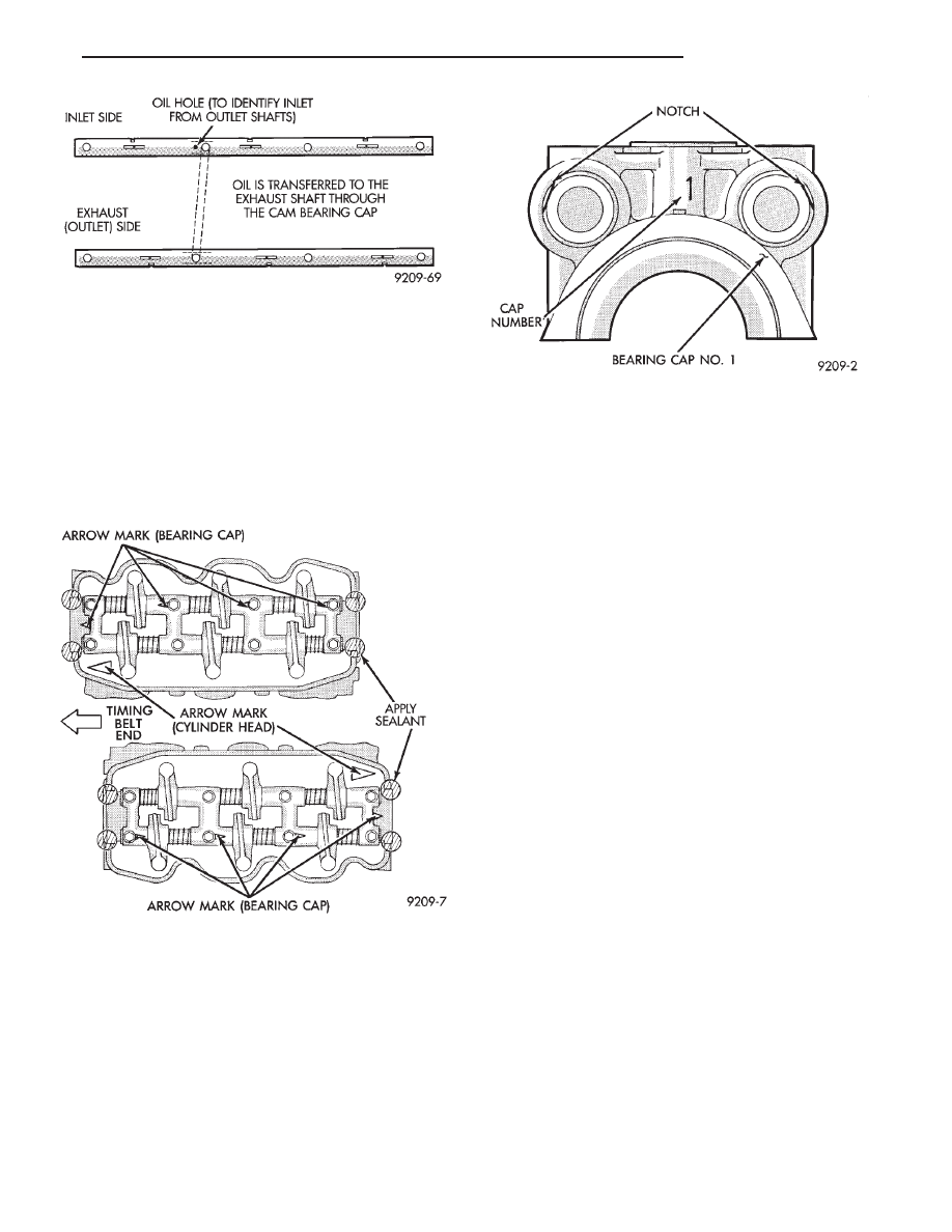
side has a 3mm diameter oil passage hole from the
cylinder head. The exhaust side does not have this
oil passage (Fig. 7).
(1) Check the rocker arm mounting portion of the
shafts for wear or damage. Replace if heavily dam-
aged or worn.
(2) Check oil holes for clogging with small wire,
clean as required (Fig. 7).
REASSEMBLE
(1) Align the camshaft bearing caps with arrows
(depending on cylinder bank) directed as shown in
(Fig. 8) and in numerical order.
Identify number one bearing cap number one and
number four caps are similar (Fig. 9).
(2) Install rocker shafts so that bearing cap num-
ber one with end notches positioned as shown in Fig-
ure 9 that the machined portion of the rocker shaft is
facing down.
(3) Insert attaching bolts to retain assembly.
ASSEMBLE ROCKER ASSEMBLY
Install the rocker arms, bearing caps and springs.
Springs are the same and can be used at all
locations on the rocker arm shafts (Figs. 8 and 10).
Insert bolts in number four bearing cap to retain
assembly.
INSTALL ROCKER ARM SHAFT ASSEMBLY
(1) Apply Mopar Silicone Rubber Adhesive Sealant
at bearing cap ends as shown in (Fig. 8).
(2) Install the rocker arm shaft assembly making
sure that the arrow mark on the bearing cap and the
arrow mark on the cylinder head are in the same
direction (Fig. 8).
The direction of arrow marks on the front and
rear assemblies are opposite to each other.
(3) Tighten bearing cap bolts in the following order
to 10 N
Im (85 in. lbs.). First #3, then #2, #1 and #4.
(4) Repeat step 3 increasing the torque to 20 N
Im
(180 in.lbs.).
(5) Install distributor drive adaptor assembly (Fig.
11).
CAMSHAFT OIL SEAL SERVICE— ENGINE
OUT OF VEHICLE
(1) Apply light coat of engine oil to the camshaft oil
seal lip.
(2) Install the oil seal using camshaft oil seal in-
staller tool MD998713 (Fig. 12).
CAMSHAFT END SEAL (PLUG) SERVICE— IN
VEHICLE SERVICE
(1) Remove air cleaner assembly from engine.
(2) Use a small punch and a hammer, carefully
remove cam plug from cylinder head.
(3) Clean the area of the cylinder head where the
new cam plug will be installed.
(4) Apply a light coating of Mopar Silicone Rubber
Adhesive Sealant to the outer diameter of the NEW
cam plug.
(5) Using a suitable installing tool and a hammer,
Fig. 7 Rocker Arm Shaft Identification
Fig. 8 Camshaft Bearing Caps Position
Fig. 9 Number One Camshaft Bearing Cap
Ä
3.0L ENGINE
9 - 77
Нет комментариевНе стесняйтесь поделиться с нами вашим ценным мнением.
Текст