Chrysler Le Baron, Dodge Dynasty, Plymouth Acclaim. Manual — part 321
TEST
EXTEND OR RETRACT ANTENNA
(1) To extend antenna, attach the positive (+) lead
of a 12 volt power source to the green antenna lead
and the negative (-) lead to the gray antenna lead.
(2) To retract antenna attach the positive (+) lead
of a 12 volt power source to the white antenna lead
and the negative (-) lead to the green antenna lead.
(3) If the motor will not operate, replace the an-
tenna assembly.
(4) If the motor runs freely and the antenna does
not extend or retract, the mast or drive assembly is
at fault.
(a) Remove the mast and verify that all the drive
teeth are intact. If not replace mast.
(b) Check for a defective drive mechanism, if de-
fective replace antenna assembly.
(5) If the mast jumps or travel rate is slow during
operation or the motor labors.
(a) Check for bent mast. If bent replace mast.
(b) Check for dirty or corroded mast. If necessary
clean and lubricate.
(c) If cleaning the antenna sections does not
solve the problem, the antenna mast should be re-
placed.
(6) If mast fails to extend or retract completely, or
motor continued to operate after full extension or re-
traction of mast.
(a) Check for broken teeth on the mast drive rod
or bent mast.
(b) Check limit switches, replace if necessary.
(7) If the mast checks good, the antenna assembly
should be replaced.
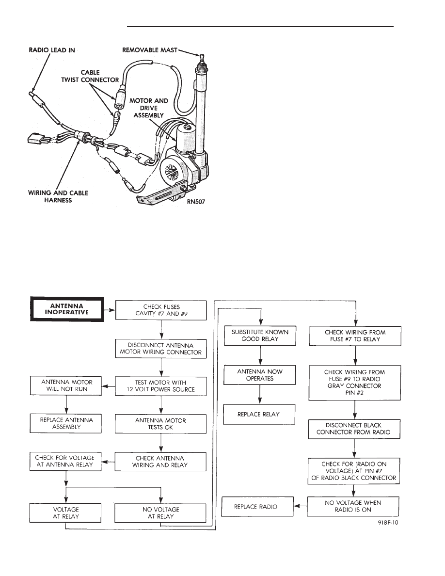
Fig. 15 Power Antenna Assembly
Fig. 16 Power Antenna Electrical Diagnosis
8F - 22
AUDIO SYSTEM
Ä
(8) Upon establishing that the fault is in the an-
tenna assembly, it may be traced to one or more of
the following conditions:
(a) Broken lead-in wire or shielding.
(b) Grounded lead-in wire or mast assembly.
(c) Moisture in support tube or lead-in assembly.
(d) Poor connection at antenna lead-in assembly
or shielding ground.
REMOVAL
(1) Disconnect battery negative cable.
(2) Remove the right front fender splash shield fas-
teners and pull shield away from the wheel housing.
(3) Disconnect motor leads at the connector (Fig. 15).
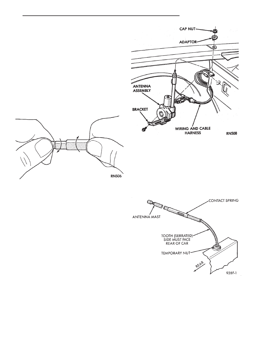
(4) Disconnect lead-in cable by twisting at connec-
tor (Fig. 17).
(5) Remove one screw attaching antenna to an-
tenna brace (Fig. 18).
(6) Remove cap nut on fender surface with An-
tenna Nut Wench C-4816 (Fig. 11).
(7) Remove antenna from under fender.
INSTALLATION
(1) Position antenna under fender and through
fender adapter.
(2) Replace and tighten cap nut to 14 N
Im (125 in.
lbs.) torque with Antenna Nut Wench C-4816.
(3) Position antenna on antenna brace and install at-
taching screw. Tighten to 4 N
Im (40 in. lbs.) torque.
(4) Connect antenna lead at twist connector.
(5) Connect motor leads at connector.
(6) Position right front fender splash shield and in-
stall attaching fasteners.
(7) Connect negative battery cable and test opera-
tion of antenna.
POWER ANTENNA MAST
REMOVAL
(1) Remove cap nut using Antenna Nut Wrench
C-4816.
(2) Install temporary nut provided with the re-
placement mast.
(3) Turn ignition key to ACCESSORY position and
turn on radio.
(4) While the mast is moving up pull upward to re-
move mast and drive rod from the mast tube.
INSTALLATION
(1) Insert new drive rod into mast tube with drive
teeth toward antenna motor (Fig. 19).
(2) Turn off radio and guide mast into tube. The
mast may not be fully lowered when first installed.
(3) Replace the temporary nut with the original
cap nut and tighten to 14 N
Im (125 in. lbs.) torque
using Antenna Nut Wench C-4816.
(4) Turn radio on and off to extend and retract an-
tenna. Mast should be fully lowered after recycling.
Fig. 18 Power Antenna Mounting
Fig. 17 Power Antenna Twist Connector
Fig. 19 Power Antenna Mast
Ä
AUDIO SYSTEM
8F - 23

SPEAKERS
INDEX
page
page
AA Body
. . . . . . . . . . . . . . . . . . . . . . . . . . . . . . . 24
AC and AY Bodies
. . . . . . . . . . . . . . . . . . . . . . . 27
AC and AY Bodies
. . . . . . . . . . . . . . . . . . . . . . . 24
AG and AJ Bodies
. . . . . . . . . . . . . . . . . . . . . . . 25
AP Body
. . . . . . . . . . . . . . . . . . . . . . . . . . . . . . . 26
Infinity Remote Amplifier
. . . . . . . . . . . . . . . . . . . 28
Relay/Choke—Infinity Speaker
. . . . . . . . . . . . . . . 29
AA BODY
FRONT DOOR MOUNTED SPEAKER
REPLACEMENT
(1) Remove power window switch.
(2) Pry out on speaker grille at two locations on
forward edge of grille to disengage clips (Fig. 20).
(3) Remove two speaker mounting screws.
(4) Pull speaker away from door and disconnect
wiring connector.
(5) For installation reverse the above procedures.
REAR DOOR MOUNTED SPEAKER
REPLACEMENT
(1) Carefully pry with a blunt edge tool at the two
slotted openings on top edge of grille to disengage
clips.
(2) Tilt top edge of grille away from door and lift
up to disengage plastic hooks on grille from trim
panel.
(3) To aid in removing speaker it may be necessary
to disengage door trim panel near speaker opening.
(4) Remove speaker-adaptor retaining screws (Fig.
21).
(5) Pull speaker away from door and disconnect
wiring connector.
(6) For installation reverse above procedures.
AC and AY BODIES
INSTRUMENT PANEL SPEAKERS
REPLACEMENT
(1) Carefully pry up at rearward corners of grille
with a blunt edge tool to disengage two plastic posts
from receptacle cavities in the instrument panel pad.
(2) As rearward edge of grille comes free of pad in-
sert your fingers under exposed grille surface and
push up to disengage two more posts at forward cor-
ners of grille.
(3) Remove two speaker attaching screws.
(4) Lift up speaker and disconnect wire connector.
Remove speaker.
(5) For installation reverse above procedures.
FRONT DOOR SPEAKER REMOVAL
(1) Remove door trim panel, refer to Group 23,
Body.
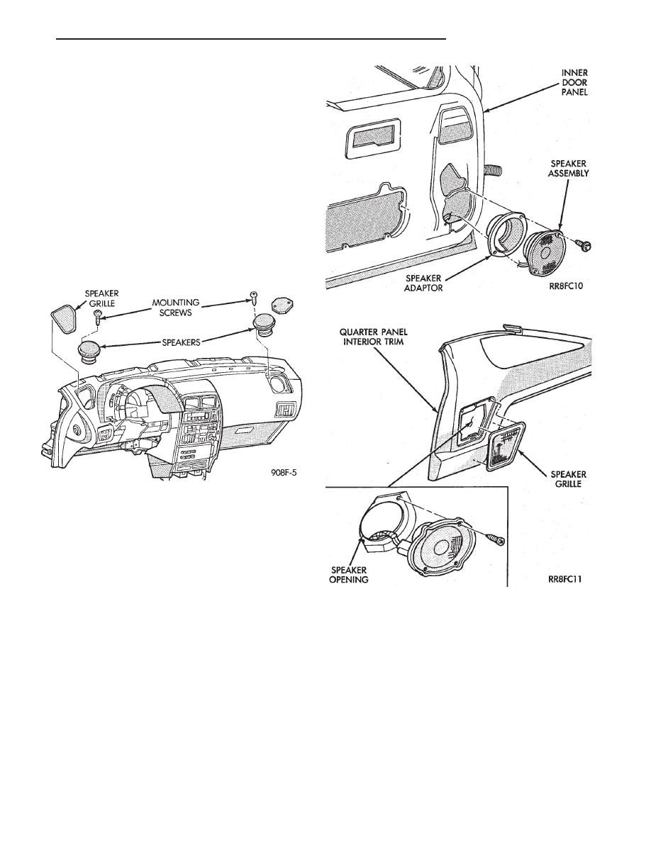
Fig. 20 Front Door Mounted Speaker—AA Body
Fig. 21 Rear Door Mounted Speaker—AA Body
8F - 24
AUDIO SYSTEM
Ä
(2) Remove two speaker attaching screws and dis-
connect wire connector.
(3) Remove speaker.
(4) For installation reverse above procedures.
REAR SHELF SPEAKERS REMOVAL
(1) Remove rear shelf, refer to Group 23, Body.
(2) Remove two speaker attaching screws and dis-
connect wire connector.
(3) Remove speaker.
(4) For installation reverse above procedures.
AG and AJ BODIES
INSTRUMENT PANEL SPEAKERS
REPLACEMENT
(1) Remove instrument panel top cover (Fig. 22).
(2) Remove two speaker retaining screws.
(3) Lift speaker away from panel and disconnect
wiring.
(4) For installation reverse above procedures.
FRONT DOOR MOUNTED SPEAKER
REPLACEMENT—AG BODY
(1) Remove door trim panel.
(2) Remove two speaker-adaptor retaining screws
(Fig. 23).
(3) Pull speaker away from door and disconnect
wiring.
(4) For installation reverse above procedures.
REAR SPEAKER REPLACEMENT—AG BODY
(1) Remove speaker grille by pulling away from
quarter trim panel to disengage retaining clips (Fig.
24).
(2) Remove four speaker retaining screws.
(3) Pull speaker away from body and disconnect
wiring.
(4) For installation reverse above procedures.
DOOR MOUNTED SPEAKER
REPLACEMENT—AJ BODY
(1) Pull speaker grille away from door trim panel
to disengage retaining clips (Fig. 25).
(2) Remove two speaker retaining screws.
(3) Pull speaker away from door and disconnect
wiring.
(4) For installation reverse above procedures.
REAR SPEAKER REPLACEMENT—AJ BODY
WITH 60/40 FOLDING REAR SEAT
(1) Remove 40-side seat back.
(2) Remove 60-side seat back.
(3) Remove outboard pivot brackets.
Fig. 22 Instrument Panel Speakers—AG and AJ
Bodies
Fig. 23 Front Door Mounted Speaker—AG Body
Fig. 24 Rear Speaker—AG Body
Ä
AUDIO SYSTEM
8F - 25
Нет комментариевНе стесняйтесь поделиться с нами вашим ценным мнением.
Текст