Chrysler Le Baron, Dodge Dynasty, Plymouth Acclaim. Manual — part 320
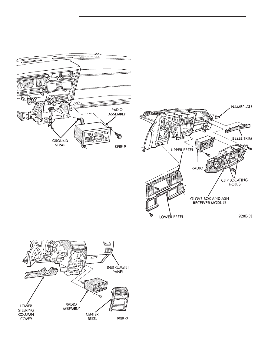
RADIO REMOVAL—AA BODY
(1) Remove center bezel by pulling straight back
disengaging the five clips.
(2) Remove radio mounting screws (Fig. 3).
(3) Pull radio from panel and disconnect wiring,
ground strap and antenna lead from radio.
(4) Remove radio.
INSTALLATION
(1) Connect wiring, ground strap and antenna lead
to radio.
(2) Position radio into panel, install mounting
screws and tighten securely.
(3) Install center bezel.
RADIO REMOVAL—AG AND AJ BODIES
(1) Remove center instrument panel bezel by pull-
ing toward the rear of the car (Fig. 4).
(2) Remove two screws attaching radio to console.
(3) Pull radio through front face of console, discon-
nect wiring harness, antenna lead, and ground strap.
INSTALLATION
(1) Position radio so that the wiring harness, an-
tenna lead, and ground strap can be connected.
(2) Install two screws attaching radio to console.
(3) Install center bezel by pushing in until clips
engage.
RADIO REMOVAL—AC AND AY BODIES
(1) Remove upper and lower bezel screws (Fig. 5)
and bezels.
(2) Remove two radio attaching screws.
(3) Disconnect wiring connectors and antenna ca-
ble.
(4) Remove screw attaching ground strap.
(5) For installation reverse above procedures.
Fig. 3 Radio Assembly—AA BODY
Fig. 4 Radio Assembly—AG and AJ Bodies
Fig. 5 Radio Assembly—AC and AY Bodies
8F - 18
AUDIO SYSTEM
Ä

RADIO REMOVAL AP BODY REPLACEMENT
(1) Remove center module bezel (Fig. 6).
(2) Remove lower center module cover if equipped
with base console.
(3) Remove right console side wall if equipped with
full console assembly.
(4) Remove two mounting screws on the radio and
pull out of instrument panel (Fig. 7).
(5) Disconnect wiring and antenna cable.
(6) Remove ground strap from radio.
(7) For installation reverse above procedures.
Fig. 6 Center Module Bezel
Fig. 7 Radio Assembly—AP Body
Ä
AUDIO SYSTEM
8F - 19

ANTENNAS
INDEX
page
page
Manual Antennas
. . . . . . . . . . . . . . . . . . . . . . . . 20
Power Antenna
. . . . . . . . . . . . . . . . . . . . . . . . . . 21
Power Antenna Mast
. . . . . . . . . . . . . . . . . . . . . . 23
MANUAL ANTENNAS
TESTING
Antenna performance may be tested by substitut-
ing a known good antenna. It is also possible to
check short or open circuits with an ohmmeter or
continuity light once the antenna cable is discon-
nected from the radio as follows:
(1) Continuity should be present between the an-
tenna mast and radio end pin of antenna cable plug
(Fig. 8 and 9).
(2) No continuity should be observed or a very
high resistance of several megohms between the
ground shell of the connector and radio end pin.
(3) Continuity should be observed between the
ground shell of the connector and the mounting hard-
ware on the vehicle fender.
REMOVAL
AA, AC and AY bodies have a short cable that
plugs into the panel harness cable.
To remove antenna, the radio must be removed
first. See radio removal. Except AA and AC bodies.
(1) Unplug antenna lead from radio receiver.
(2) Remove antenna mast by unscrewing mast
from antenna body (Fig. 10).
(3) Remove cap nut with Antenna Nut Wrench
C-4816 (Fig. 11).
(4) Remove antenna adapter and gasket (Fig. 12).
(5) Unfasten three push pins from the rear of the
plastic inner fender shield and bend the shield away
to gain access to the antenna body.
(6) From under fender remove antenna lead and
body assembly (Fig. 12).
Fig. 8 Antenna Test Points
Fig. 9 Antenna Test Points—Two Piece Cable
Fig. 10 Antenna Mast Removal and Installation
8F - 20
AUDIO SYSTEM
Ä
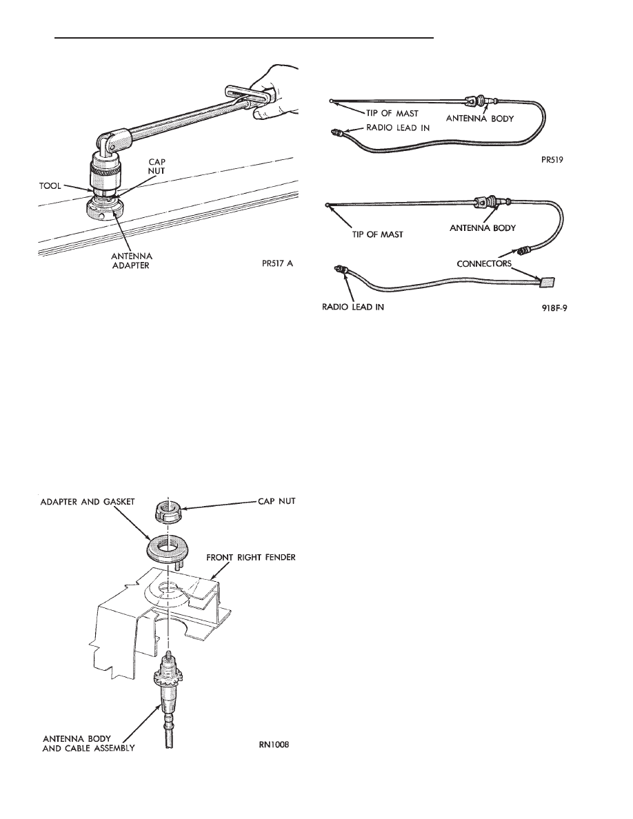
INSTALLATION
(1) Install antenna body and cable from under-
neath fender (Fig. 12).
(2) Install gasket, adapter, and cap nut. Tighten
cap nut to 14 N
Im (125 in. lbs.) with Antenna Nut
Wrench C-4816.
(3) Install antenna mast into antenna body until
sleeve bottoms on antenna body (Fig. 11).
(4) Route cable to radio if necessary.
BENCH TEST FOR ANTENNA MALFUNCTION
It is also possible to check short or open circuits
with an ohmmeter or continuity light once the an-
tenna has been removed from the vehicle.
(1) Continuity should be present between the tip of
the mast and radio end pin (Fig. 13 and 14).
(2) No continuity should be observed or a very high
resistance of several megohms between the ground
shell of the connector and radio end pin.
(3) Continuity should be observed between the ground
shell of the connector and the mounting hardware.
Wiggle cable over its entire length to reveal inter-
mittent short or open circuits during step 1, 2 and 3.
POWER ANTENNA
OPERATION
The power operated radio antenna (Fig. 15) is a
telescoping type antenna, extended and retracted by a
reversible electric motor.
The Automatic Power Antenna is controlled by a
combination of an external relay and limit switches
built into the antenna motor housing. The antenna is
actuated when radio is switched ON and the ignition
switch in ON or ACCESSORY position. The antenna
mast should extend. When the ignition switch or radio
is turned OFF the antenna mast should fully retract
and declutch.
Many antenna problems may be avoided by frequent
cleaning of the antenna mast telescoping sections. Clean
the antenna mast sections with a clean soft cloth.
Before an antenna is removed, the antenna perfor-
mance should be tested to decide if it is a reception
problem or an operational problem.
Whenever an operational malfunction occurs, first
verify that the radio antenna wire harness is properly
connected. Check all connectors before starting normal
diagnosis and repair procedures. Refer to Power An-
tenna Electrical Diagnosis Chart (Fig. 16).
Fig. 12 Antenna Mounting
Fig. 11 Removing or Tightening Antenna Cap Nut
Fig. 13 Antenna Bench Test Points
Fig. 14 Antenna Bench Test Points—Two Part
Ä
AUDIO SYSTEM
8F - 21
Нет комментариевНе стесняйтесь поделиться с нами вашим ценным мнением.
Текст