Chrysler Le Baron, Dodge Dynasty, Plymouth Acclaim. Manual — part 74
AUTOMATIC TRANSMISSION SHIFTER/IGNITION INTERLOCK
INDEX
page
page
General Information
. . . . . . . . . . . . . . . . . . . . . . . 36
Interlock System Adjustment
. . . . . . . . . . . . . . . . 37
Interlock System Operation Check
. . . . . . . . . . . . 36
Shifter/Ignition Interlock Cable
. . . . . . . . . . . . . . . 38
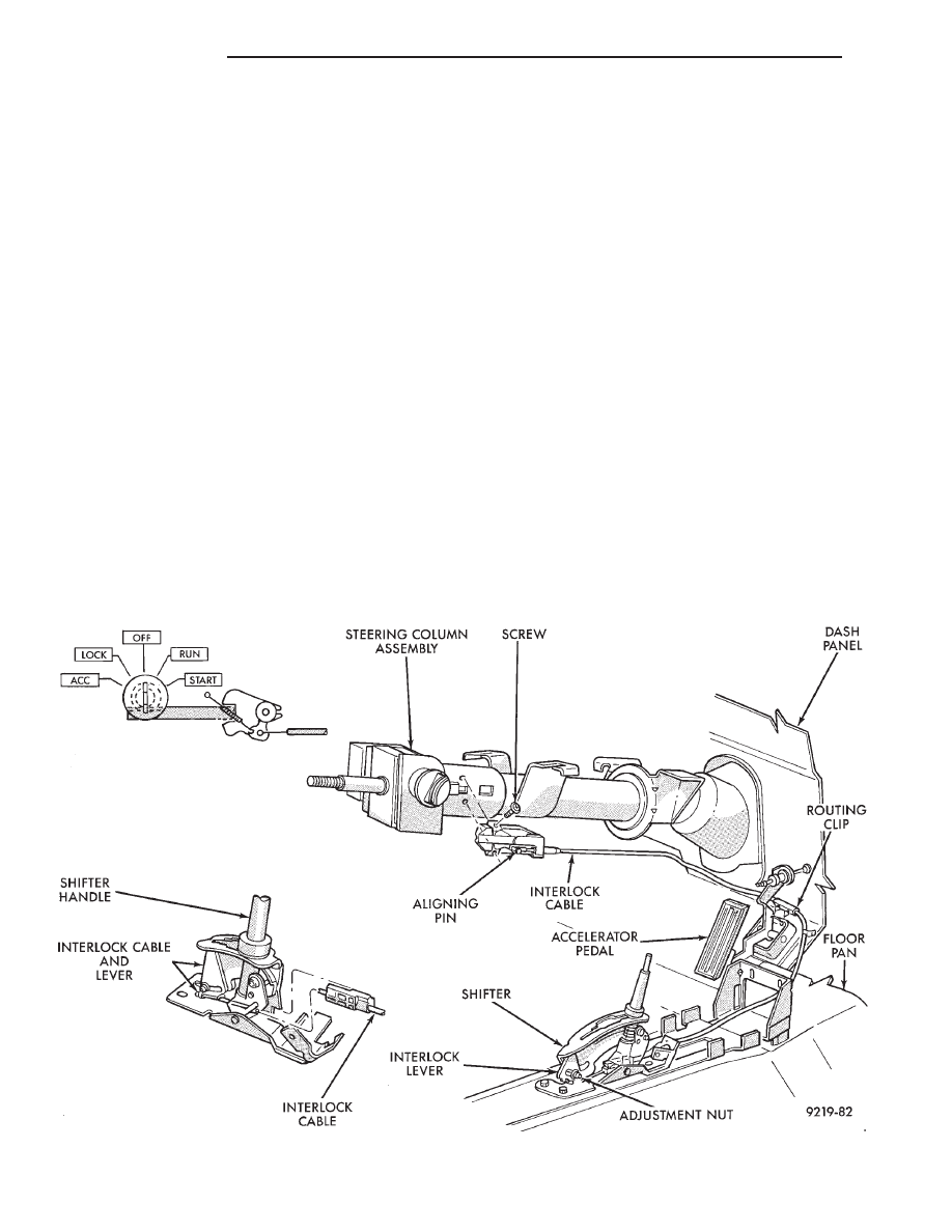
GENERAL INFORMATION
The automatic transmission Shifter/Ignition Inter-
lock, is a mechanically cable operated system (Fig.
1). It interconnects the automatic transmission floor
mounted shifter to the steering column ignition
switch. The interlock system locks the floor mounted
shifter on automatic transmission equipped vehicles
into the PARK position. The Interlock system is en-
gaged whenever the ignition switch is in the LOCK
or ACCESSORY position. When the key is in the
OFF or RUN position the shifter is unlocked and will
move into any position. The interlock system also
prevents ignition switch from being turned to the
OFF or ACCESSORY position, unless shifter is fully
locked into the PARK position.
INTERLOCK SYSTEM OPERATION CHECK
(1) With the shifter in PARK, and the shifter knob
pushbutton in its full up position, the ignition switch
should rotate freely from OFF to LOCK position.
When the shifter is moved to the DRIVE (or OVER-
DRIVE) position if so equipped the ignition switch
should not rotate from OFF to LOCK.
(2) Moving shifter out of PARK should only be pos-
sible when ignition switch is in the OFF or RUN po-
sition. Movement of the shifter from the PARK
position should not be possible, when the ignition
switch is in the LOCK position.
(3) If the automatic transmission Shifter/Ignition
Interlock System operates in any way other than as
described above, diagnosis, adjustment or repair of
the system is required. See Adjustment and Repair
procedures in this section of the service manual.
Fig. 1 Shifter Ignition Interlock System Components
19 - 36
STEERING
Ä
INTERLOCK SYSTEM ADJUSTMENT
If ignition switch is binding, operating effort high or
can not
be turned to the LOCK position, with shifter locked
in PARK, adjustment of Interlock System may be
required. To adjust Interlock System, follow procedure
listed below.
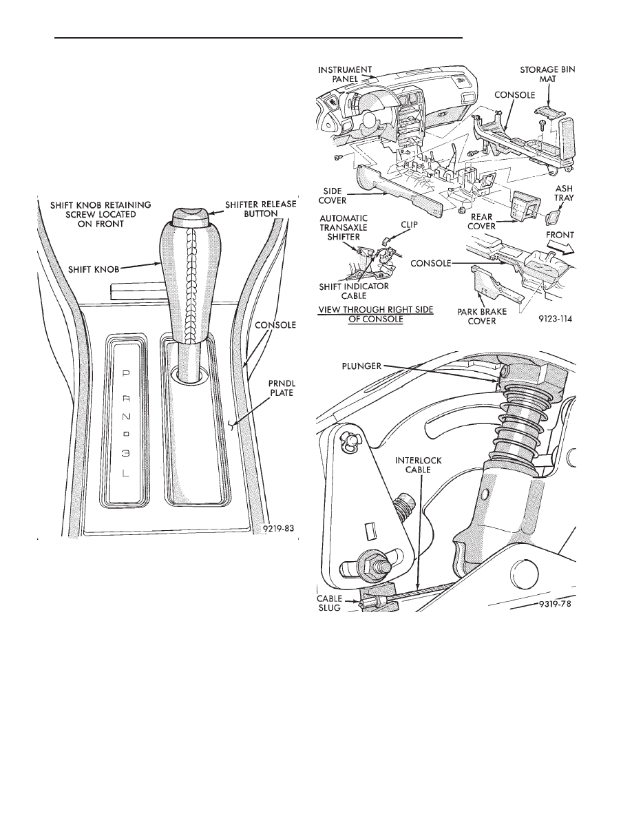
(1) Remove the shift knob to shifter retaining screw
and shift knob from shifter (Fig. 2). Leave the shifter
release button in shifter handle.
(2) On the AA and AP bodies, remove PRNDL plate
(Fig. 2) from center console for adjustment of interlock
cable. PRNDL plate is removed by gently prying be-
tween plate and console with a screw driver. Use care
so not to damage plate or console assembly.
(3) On the AG and AJ bodies, the center console
(Fig. 3) requires removal from vehicle for adjustment of
interlock cable. Refer to the AG or AJ section of Group
23 Body, in this service manual for detailed center
console removal procedure.
(4) Place shifter in PARK, and ensure that the
plunger (Fig. 4) on shifter mechanism is in the full up
position.
(5) Turn ignition switch to the ACCESSORY posi-
tion. The Interlock System will not adjust prop-
erly if the ignition switch is in the LOCK
position. If interlock cable has lost its adjustment, it
will be necessary to manually position cable to get
key into Accessory position. Grasp slug on interlock
cable (Fig. 5) with needle nose pliers and pull back
on cable. This will allow the ignition switch to be
turned to the ACCESSORY position.
(5) Check that the interlock cable slug is com-
pletely seated into the shifter interlock lever (Fig. 4).
(6) Check that the ignition switch is still in the ac-
cessory position (Fig. 1). Loosen the shifter interlock
Fig. 3 AG & AJ Center Console
Fig. 4 Plunger Position For Interlock Adjustment
Fig. 2 Removing Shift Knob And PRNDL Plate
Ä
STEERING
19 - 37
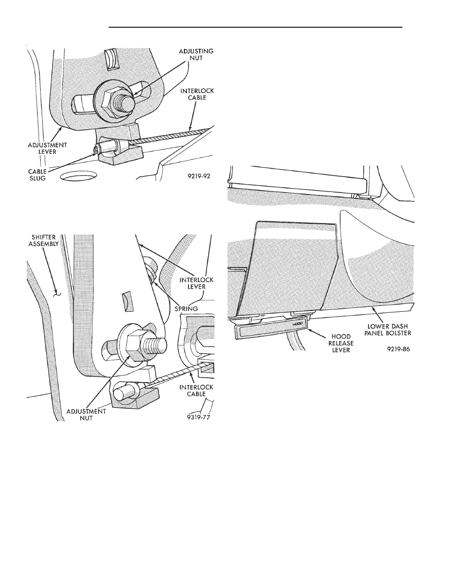
lever adjustment nut, (Fig. 6) enough to allow the
spring to correctly position the interlock lever on the
shifter assembly.
(7) Then torque the interlock lever adjustment nut
to 2 N
Im (15 in. lbs.) minimum 3 NIm (25 in. lbs.)
maximum.
(8) On the AA and AP bodies, install the PRNDL
plate (Fig. 2) back into the center console.
(9) On the AG and AJ bodies, install the center
console (Fig. 3) back into the vehicle. Refer to the
AG or AJ section of Group 23 Body, in this service
manual for detailed center console installation proce-
dure.
(10) Install the shift knob onto the shifter assem-
bly. Install the shift knob to shifter retaining screw
and torque to 3 N
Im (25 in.lbs. ) (Fig. 2).
(11) After adjusting the interlock system, perform
the interlock system operation check. See Interlock
System Operation Check in this section of the service
manual.
SHIFTER/IGNITION INTERLOCK CABLE
REMOVE
(1) Disconnect and isolate, the battery negative (-)
cable from the vehicle battery.
(2) Remove the lower dash panel bolster and inside
hood release lever, (Fig. 5) from the vehicle instru-
ment panel.
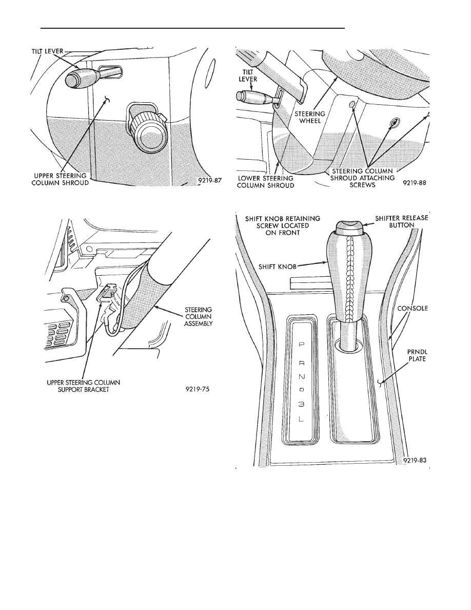
(3) Remove the tilt lever (Fig. 6) (if so equipped)
from the steering column assembly.
(4) Remove the 3 screws mounting upper steering
column shrouds to steering column assembly and
then remove the shrouds (Fig. 6).
(5) Remove the 2 nuts holding the upper steering
column mounting bracket, to the steering column
support bracket (Fig. 7). Lower steering column for
clearance when removing lower shrouds from steer-
ing column.
(6) Remove the 3 screws mounting the lower steer-
ing column shroud to the steering column assembly
and remove shroud (Fig. 8).
(7) Remove shift knob to shifter retaining screw
and remove knob from shifter assembly. Remove
PRNDL plate from the console assembly (Fig. 9).
(8) Remove center console assembly. Refer to
Group 23 Body, in this service manual for the appro-
priate procedure for body style being serviced.
Fig. 5 Interlock Cable Slug
Fig. 6 Adjusting Interlock Lever
Fig. 5 Remove Hood Release lever And Dash Panel
Bolster
19 - 38
STEERING
Ä
(9) Loosen but do not remove the interlock lever
adjusting nut (Fig. 10) on the shifter assembly.
(10) Remove interlock cable slug, from interlock le-
ver on shifter assembly (Fig. 10). Remove interlock
cable from shifter assembly by grasping cable and
pulling straight out from front of shifter assembly
(Fig. 11).
(11) Remove the interlock cable routing clip from
the throttle pedal bracket (Fig. 12). Removal of the
clip can be done by using needle nose pliers to com-
press barbs on clip and removing from holes in
bracket.
(12) Remove the 2 screws holding the interlock
mechanism to the steering column (Fig. 13). Mecha-
nism is held to column by clips on back of mecha-
nism,
then
pull
mechanism
straight
out
from
steering column.
(13) Remove interlock cable from routing clip on
lower steering column mounting bracket.
(14) Route interlock cable from under center con-
sole mounting bracket and out front of dash panel.
Fig. 6 Upper Steering Column Shroud And Tilt
Lever
Fig. 7 Steering Column Mounting Bracket
Fig. 8 Lower Steering Column Shroud
Fig. 9 Shift Knob And PRNDL Plate Removal
Ä
STEERING
19 - 39
Нет комментариевНе стесняйтесь поделиться с нами вашим ценным мнением.
Текст