Chrysler Le Baron, Dodge Dynasty, Plymouth Acclaim. Manual — part 75
INSTALL
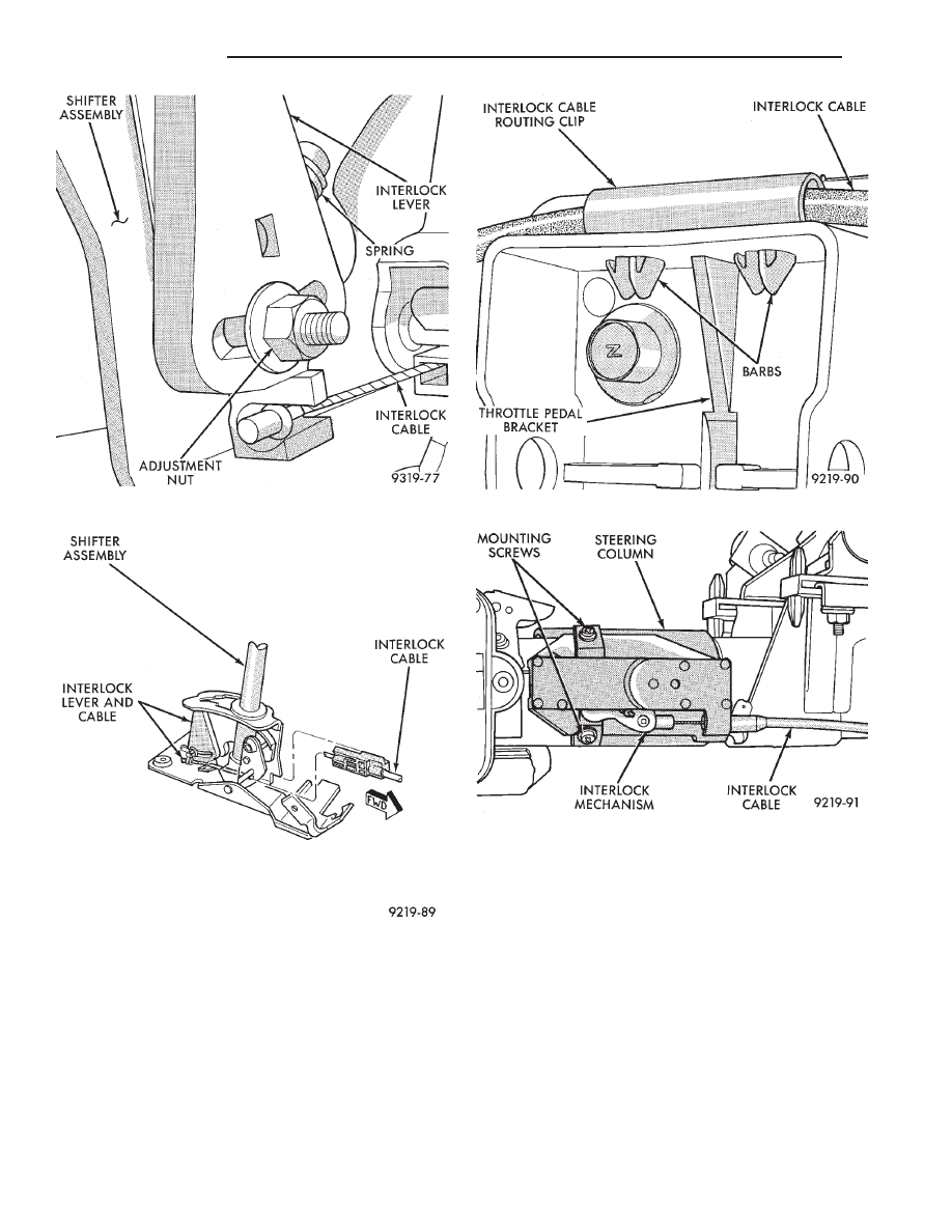
CAUTION: When installing interlock cable assem-
bly, care must be taken not to bend exposed cable
wire and slug at shifter end of cable.
(1) Route interlock cable into lower dash panel and
down under the center console mounting bracket
(Fig. 1). Cable must be routed above the lower dash
panel support bracket and above throttle pedal base.
(2) Turn the ignition switch to the RUN position
(Fig. 1). Install the interlock mechanism on the
steering column, by locking tabs on back of mecha-
nism into large square opening on steering column.
(3) Move cam on interlock mechanism by hand, al-
lowing slider to move into cam and ignition switch to
rotate to the ACCESSORY position. Then turn the
ignition switch to the ACCESSORY position (Fig. 1).
(4) Install the 2 interlock mechanism to steering
column attaching screws (Fig. 13) and torque to 3
N
Im (21 in. lbs.).
(5) Install interlock cable into routing clip on
lower steering column mounting bracket.
Fig. 10 Interlock Adjusting Nut
Fig. 11 Interlock Cable Removal
Fig. 12 Remove Interlock Routing Clip
Fig. 13 Removing Interlock Mechanism
19 - 40
STEERING
Ä
CAUTION:
Interlock
cable
must
by
completely
clipped to the throttle pedal bracket with both barbs
of clip fully installed through mounting holes. This
is to prevent interference with throttle pedal.
(6) Snap the interlock cable routing clip into the 2
holes on the throttle pedal mounting bracket (Fig.
12).
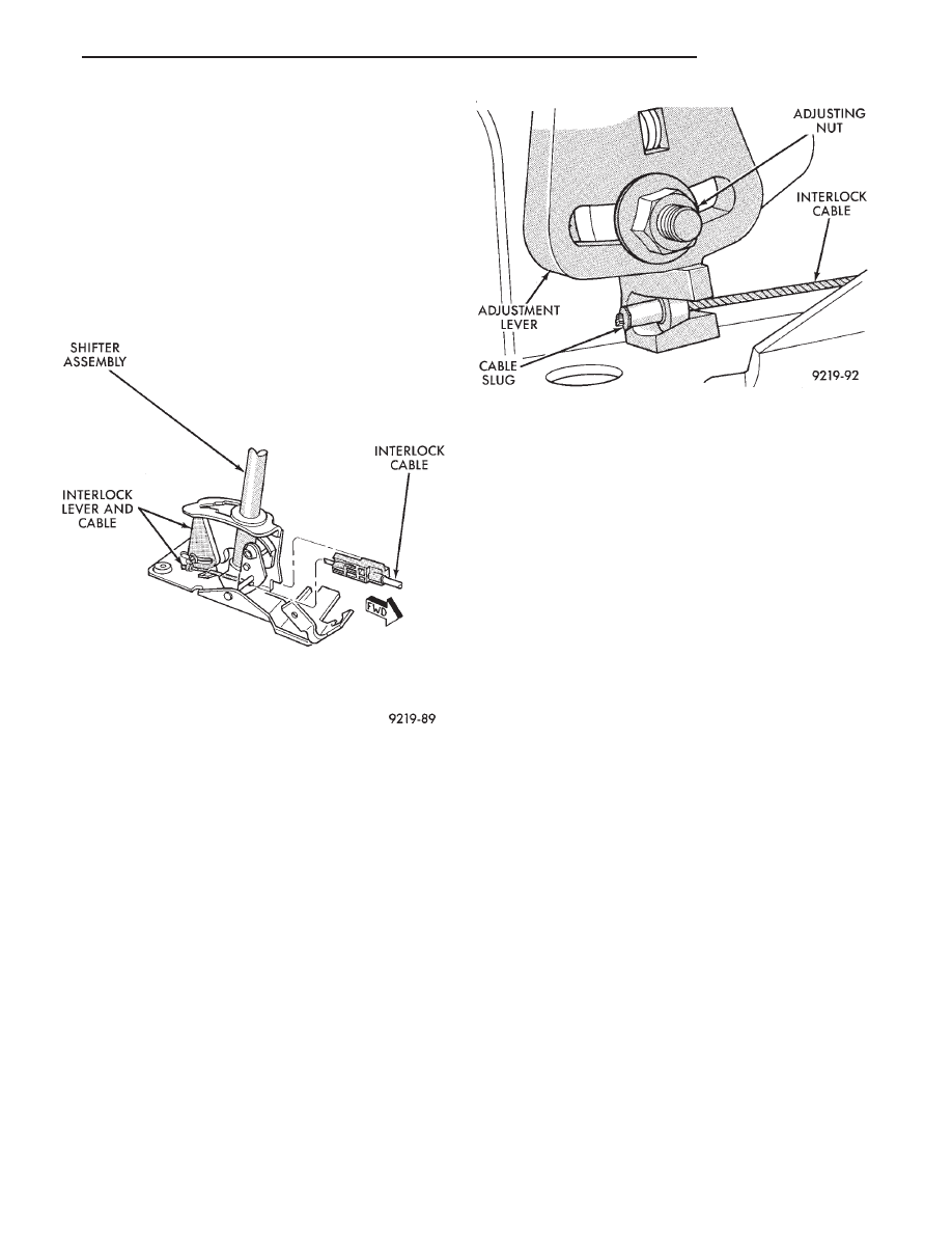
(7) Snap the end fitting of the interlock cable into
the corner of the shifter assembly (Fig. 14). The cable
end and clip must pass under and clip to the shifter
pivot.
(8) Install slug on end of interlock cable into notch,
on shifter lockout spring loaded lever (Fig. 15). Make
sure that cable slug is fully seated in cup of lever as-
sembly.
(9) Adjust the Shifter/Ignition Interlock System.
See Interlock System Adjustment, in this section of
service manual.
(10) Perform the Shifter/Ignition Interlock System
operation check, as described in the beginning of this
section.
(11) Install
center
console
assembly.
Refer
to
Group 23 Body, in this service manual for the appro-
priate procedure for the body style
being serviced.
(12) Install PRNDL plate in center console. Install
the shift knob onto the shifter assembly. Install the
shift knob to shifter retaining screw and torque to 3
N
Im (25 in.lbs.) (Fig. 2).
(13) Install the lower steering column shrouds on
the steering column (Fig. 8). Tighten the 2 lower
shroud to steering column screws.
(14) Make sure ground clip is on left breakaway
capsule. Make sure that both breakaway capsules are
fully seated in the upper steering column bracket. In-
stall the upper steering column mounting bracket
onto the steering column support bracket (Fig. 7). In-
stall the 2 upper steering column bracket to support
bracket nuts and torque to 12 N
Im (105 in. lbs.).
(15) Install the upper steering column shrouds on
the steering column (Fig. 6). Tighten the 3 upper
shroud to steering column attaching screws.
(16) Install the tilt lever (Fig. 6) (if so equipped)
back on the steering column assembly.
(17) Install the lower dash panel bolster. Install
bolster attaching screws and torque to 3 N
Im (24 in.
lbs.). Install the inside hood release lever and torque
screws to 3 N
Im (24 in. lbs.) (Fig. 5).
(18) Reconnect the battery negative (-) cable to the
vehicle battery.
Fig. 14 Interlock Cable Installation
Fig. 15 Install Interlock Cable In Shifter
Ä
STEERING
19 - 41
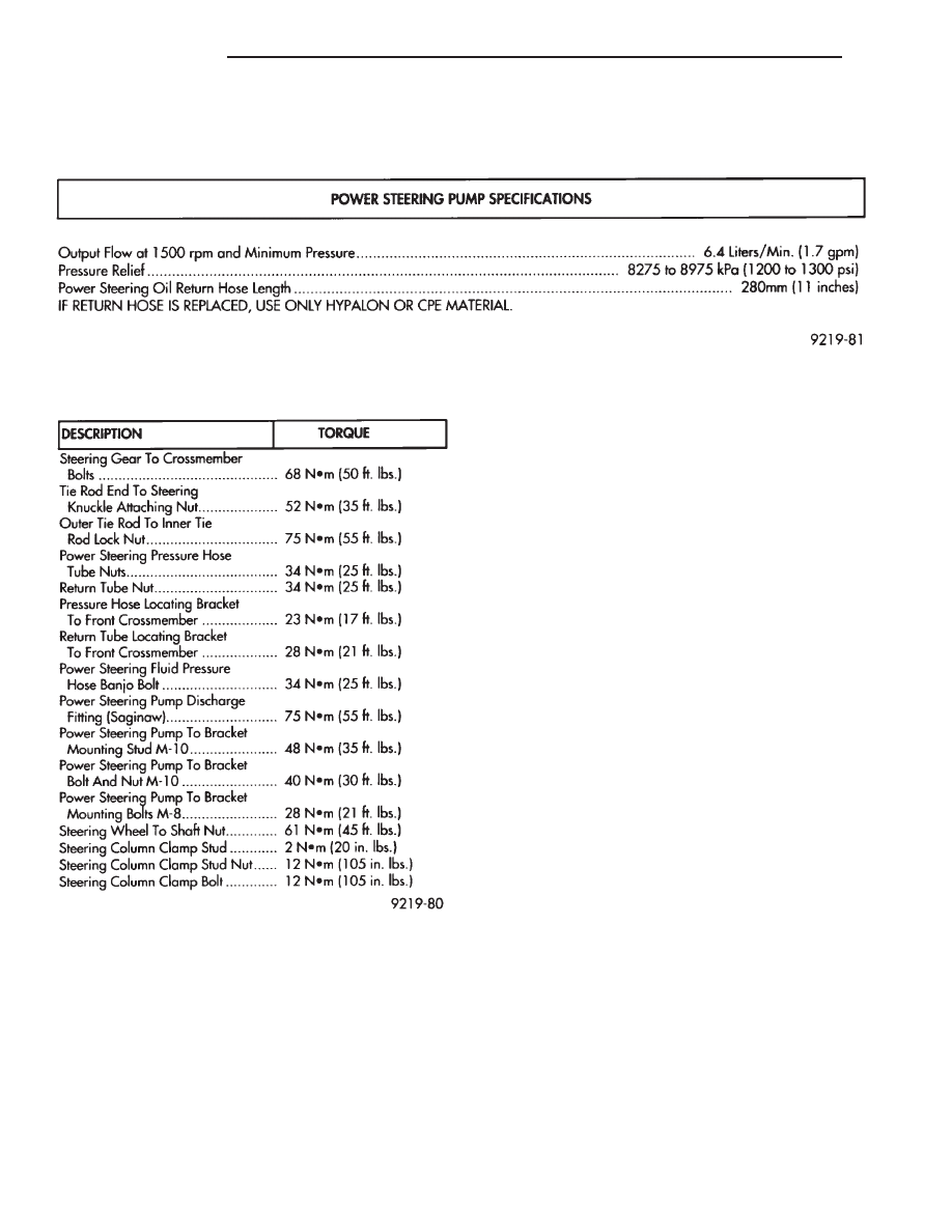
SPECIFICATIONS AND TIGHTENING REFERENCE
POWER STEERING PUMP SPECIFICATIONS
TORQUE SPECIFICATIONS
19 - 42
STEERING
Ä
SUSPENSION AND DRIVESHAFTS
CONTENTS
page
page
AUTOMATIC AIR LOAD LEVELING SYSTEM
. 59
AUTOMATIC AIR SUSPENSION
. . . . . . . . . . . . 73
DRIVESHAFTS
. . . . . . . . . . . . . . . . . . . . . . . . . 25
FRONT SUSPENSION
. . . . . . . . . . . . . . . . . . . . . 2
FRONT SUSPENSION SERVICE PROCEDURES . 5
GENERAL INFORMATION . . . . . . . . . . . . . . . . . . 1
REAR (STUB) AXLE ALIGNMENT ALL
MODELS
. . . . . . . . . . . . . . . . . . . . . . . . . . . . 89
REAR SUSPENSION
. . . . . . . . . . . . . . . . . . . . . 50
SPECIFICATIONS
. . . . . . . . . . . . . . . . . . . . . . . 91
GENERAL INFORMATION
Throughout this group, references may be made to
a particular vehicle by letter or number designation.
A chart showing the breakdown of these designations
is included in the Introduction section at the front of
this Service Manual.
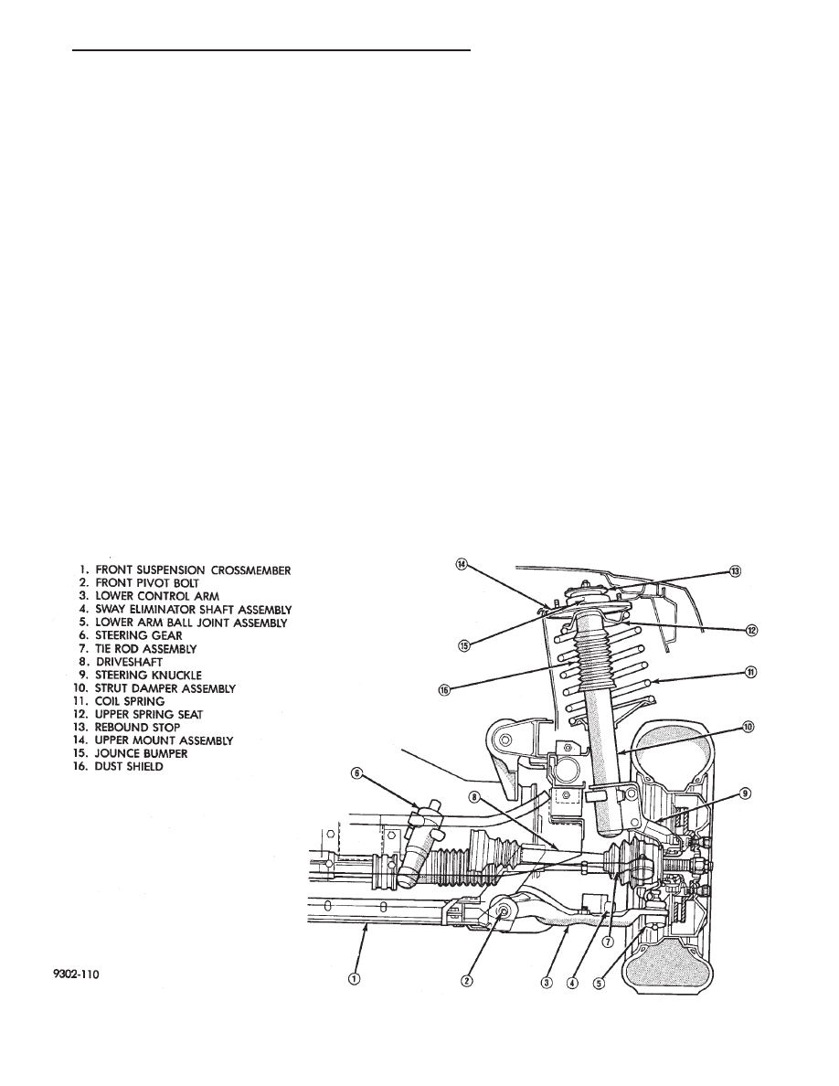
An independent MacPherson Type front suspension
is used on these vehicles. Vertical shock absorbing
struts attach to the upper fender reinforcement and
the steering knuckle to provide upper steering
knuckle position. Lower control arms are attached
inboard to a crossmember and outboard to the steer-
ing knuckle through a ball joint to provide lower
steering knuckle position. During steering maneu-
vers, the strut (through a pivot bearing in the upper
retainer) and the steering knuckle turn as an assem-
bly (Fig. 1).
Fig. 1 Front Suspension (Typical)
Ä
SUSPENSION AND DRIVESHAFTS
2 - 1
Нет комментариевНе стесняйтесь поделиться с нами вашим ценным мнением.
Текст