Chrysler Le Baron, Dodge Dynasty, Plymouth Acclaim. Manual — part 343

• The Illuminated Entry Diagnosis—AC, AG, AJ
and AY-BODY chart in this section.
• The Illuminated Entry System section of the ap-
propriate Body Diagnostic Procedures Manual.
• The Wiring Diagrams Manual.
ILLUMINATED ENTRY MODULE—AA-BODY
REMOVAL
(1) Disconnect the battery negative cable.
(2) Remove the glove box to gain access to the
module (Fig. 2). Refer to Group 8E, Instrument Panel
and Gauges.
(3) Working through the glove box opening, discon-
nect the wiring connector at the module.
(4) Remove the module bracket mounting screw.
(5) Remove the module bracket from the vehicle.
INSTALLATION
Reverse the preceding operation.
BODY CONTROLLER COMPUTER—AC, AG, AJ and
AY-BODY
REMOVAL
The Body Controller Computer is located at the
right front door opening behind the cowl trim panel
(Fig. 3).
(1) Remove the battery negative cable before re-
moving the Body Controller.
(2) Remove screws holding cowl trim and door
opening scuff plate to cowl panel.
(3) Disconnect wire connectors from body control-
ler.
(4) Remove nuts holding body controller to cowl
panel.
(5) Separate body controller from vehicle.
INSTALLATION
Reverse the preceding operation.
Fig. 3 Body Controller
Fig. 4 Illuminated Entry Circuit Wiring—AA-Body
Fig. 5 Module Pin Outs—AA-Body
8L - 34
LAMPS
Ä
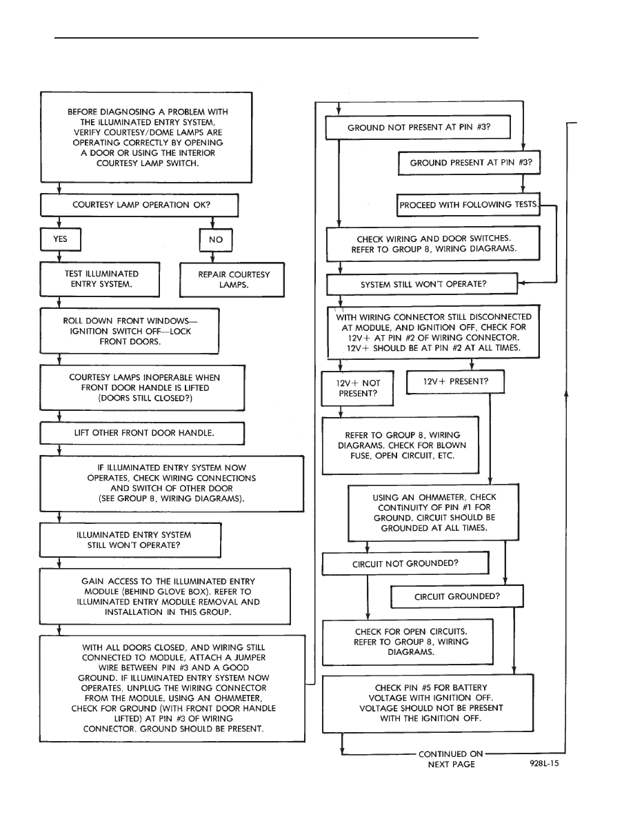
ILLUMINATED ENTRY DIAGNOSIS—AA-BODY
Ä
LAMPS
8L - 35
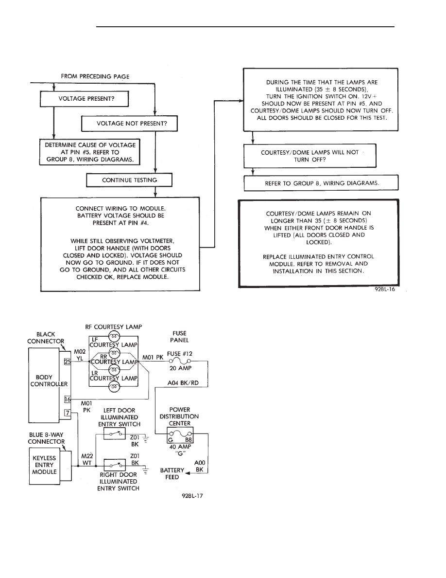
ILLUMINATED ENTRY DIAGNOSIS (CONT.)—AA-BODY
Fig. 6 Illuminated Entry Circuit Wiring—AC, AG, AJ
and AY- Body—Typical
8L - 36
LAMPS
Ä

ILLUMINATED ENTRY DIAGNOSIS—AC, AG, AJ AND AY-BODY
Ä
LAMPS
8L - 37
Нет комментариевНе стесняйтесь поделиться с нами вашим ценным мнением.
Текст