Chrysler Le Baron, Dodge Dynasty, Plymouth Acclaim. Manual — part 342
(2) Open hood and locate Power Distribution Cen-
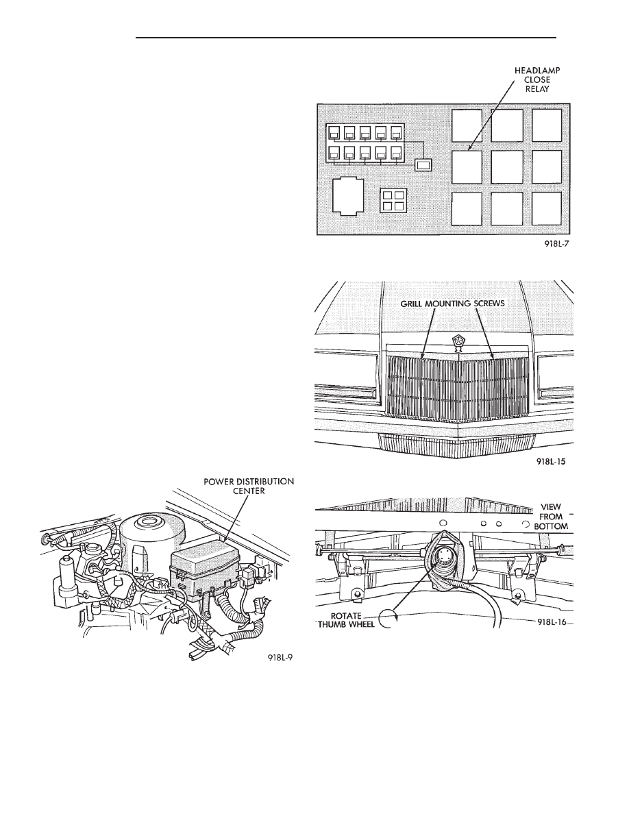
ter forward of the left suspension tower (Fig. 3).
(3) Remove cover from the center and pull the
Headlamp Close Relay (Fig. 4) to keep the headlamp
doors from closing.
(4) Turn headlight switch OFF.
(5) Remove two grill mounting screws and remove
grill assembly (Fig. 5).
(6) Spring tension must be relieved from the head-
lamp doors before removing headlamp motor torsion
bar clips. Locate the thumb wheel on bottom of head-
lamp motor (Fig. 6). Rotate thumb wheel approxi-
mately six to seven turns clockwise to relieve all
tension.
(7) Remove torsion bar anchor clip (Fig. 7).
(8) Slide torsion bar sleeve over the torsion bar
(Fig. 8).
(9) Remove three clips retaining turn signal lamp
shield to body (Fig. 9), and remove shield.
(10) Remove two screws retaining headlamp cover
to headlamp cover bracket (Fig. 10).
(11) Remove outer headlamp.
(12) Remove outer pivot screw (Fig. 11).
(13) Remove E-clip and door crank screw (Fig. 12).
(14) Remove three bolts retaining cam pivot to
body and remove cam pivot (Fig. 11).
(15) Remove Headlamp door assembly.
INSTALLATION
Reverse the preceding operation. Before installing
torsion bar clips, the holes in the torsion bars, tor-
sion bar sleeves and headlamp door cam pivots must
be in alignment. Refer to Aligning Headlamp Doors.
HEADLAMP DRIVE MOTOR—AY BODY
REMOVAL
(1) Open headlamp doors. Refer to Headlamp Door
paragraph for instructions.
(2) Remove grill mounting screws and remove grill
assembly (Fig. 5).
(3) Spring tension must be relieved from headlamp
doors before removing the headlamp motor torsion
bar clips. Locate the thumb wheel on bottom of the
headlamp motor (Fig. 6). Rotate thumb wheel ap-
proximately six to seven turns (clockwise) to relieve
all tension.
(4) Remove both torsion bar anchor clips (Fig. 7).
(5) Slide torsion bar sleeves over the torsion bar
(Fig. 8).
Fig. 3 Power Distribution Center
Fig. 4 Headlamp Close Relay
Fig. 5 Grill
Fig. 6 Headlamp Motor—Bottom View
8L - 30
LAMPS
Ä

(6) Disconnect wire connector from motor.
(7) Remove motor mounting bolts (Fig. 11).
(8) Slide torsion bar through the headlamp motor
(Fig. 13) and remove headlamp motor.
INSTALLATION
Reverse the preceding operation. Before installing
torsion bar clips, the holes in the torsion bars, tor-
sion bar sleeves and headlamp door cam pivots must
be in alignment.
HEADLAMP DOOR ALIGNMENT
Door stop adjustment screws, and a movable cam
pivot are used to adjust and align the headlamp
doors.
Fig. 9 Front Turn Signal Lamp Shield
Fig. 10 Headlamp Cover/Cover Pivot Bracket
Fig. 7 Torsion Bar Anchor Clips
Fig. 8 Torsion Bar Sleeves
Fig. 11 Outer Pivot Screw
Fig. 12 Headlamp Pivot E-Clip and Crank Screw
Ä
LAMPS
8L - 31

Loosening the cam pivot bolts (Fig. 14) will allow
an up/down or in/out adjustment of the headlamp
doors.
The stop screws (Fig. 14) are also used to achieve
proper tolerances.
Fig. 13 Headlamp Motor
Fig. 14 Cam Pivot Adjustment
8L - 32
LAMPS
Ä

ILLUMINATED ENTRY SYSTEM
INDEX
page
page
Body Controller Computer—AC, AG, AJ and
. . . . . . . . . . . . . . . . . . . . . . . . . . . . . 34
Diagnostic Procedures—AC, AG, AJ and AY-Body . 33
General Information
. . . . . . . . . . . . . . . . . . . . . . . 33
Illuminated Entry Module—AA-Body
GENERAL INFORMATION
AA-BODY
The Illuminated Entry System (on AA Body) actu-
ates the interior courtesy and/or dome lamps (except
for the illuminated ignition switch) by lifting either
front door exterior handle.
Lamp illumination is terminated 35 seconds (
6 8
seconds later when battery voltage is normal), or by
turning the ignition switch to the run position,
whichever occurs first. When testing the system, all
vehicle doors must be closed to prevent the door jam
switches from activating the courtesy/dome lamps.
Front door handle switches (Fig. 1), and the Illumi-
nated Entry Module (located behind and above the
glove box (Fig. 2) are used to control the system.
Depending on vehicle options, as many as six dif-
ferent electrical components/relays are located above
the glove box. The Illuminated Entry Module will be
the one mounted the closest to the outside of the in-
strument panel. The Module bracket is also used to
commonly mount the Power Door Lock Inhibitor Re-
lay, if equipped.
Service procedures for door related components can
be found in Group 23, Body.
AC, AG, AJ OR AY BODY
The Illuminated Entry System (AC, AG, AJ or AY
Body) actuates the interior courtesy and/or dome
lamps (except illuminated ignition switch) by lifting
either front door exterior handle. Activation can also
be accomplished with the remote keyless entry sys-
tems hand held module, if equipped.
Lamp illumination is terminated 30 seconds (
6 2
seconds) later, or by turning the ignition switch to
the run position, whichever occurs first. When test-
ing this system, all vehicle doors must be closed to
prevent the operation of the courtesy/dome lamps.
Front door handle switches (Fig. 1), and the Body
Controller (Fig. 3 ) are used to control the system.
Service procedures for door related components can
be found in Group 23, Body.
DIAGNOSTIC PROCEDURES—AA-BODY
For diagnostics and wiring schematics, refer to:
• The Illuminated Entry Diagnosis—AA-Body chart
in this section.
• The Wiring Diagrams Manual.
• Fig. 4 and 5.
DIAGNOSTIC PROCEDURES—AC, AG, AJ AND
AY-BODY
For diagnostics and wiring schematics, refer to:
Fig. 1 Illuminated Entry Door Switches—Typical
Fig. 2 Illuminated Entry Module—AA Body
Ä
LAMPS
8L - 33
Нет комментариевНе стесняйтесь поделиться с нами вашим ценным мнением.
Текст