Chrysler Le Baron, Dodge Dynasty, Plymouth Acclaim. Manual — part 42
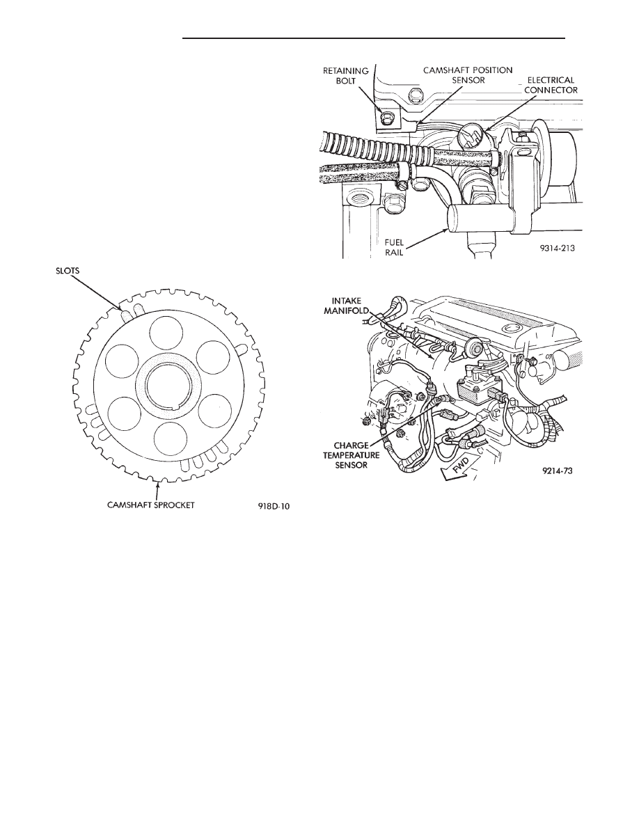
The camshaft position sensor senses when a notch in
the camshaft gear passes beneath it (Fig. 4). When
metal aligns with the sensor, voltage goes low (less
than 0.3 volts). When a notch aligns with the sensor,
voltage spikes high (5.0 volts). As a group of notches
pass under the sensor, the voltage switches from low
(metal) to high (notch) then back to low. The number of
notches determine the amount of pulses. If available,
an oscilloscope can display the square wave patterns of
each timing events.
Top dead center (TDC) does not occur when notches
on the camshaft sprocket pass below the cylinder. TDC
occurs after the camshaft pulse (or pulses) and after
the 4 crankshaft pulses associated with the particular
cylinder.
The camshaft position sensor is mounted on the top
of the cylinder head (Fig. 5). The bottom of the sensor
is positioned above the camshaft sprocket. The dis-
tance between the bottom of sensor and the
camshaft sprocket is critical to the operation of
the system. When servicing the camshaft posi-
tion sensor, refer to the 2.2L Turbo III Multi-Port
Fuel Injection—Service Procedures section in
this Group.
CHARGE AIR TEMPERATURE SENSOR—PCM IN-
PUT
The charge air temperature sensor is mounted to
intake manifold. The sensor measures the temperature
of the air-fuel mixture (Fig. 6). This information is used
by the PCM to modify air/fuel mixture and turbo-
charger boost level.
ENGINE COOLANT TEMPERATURE SENSOR—PCM
INPUT
The coolant temperature sensor is a variable resis-
tor with a range of -40°C to 128°F (-40°F to 265°F).
The sensor is installed into the thermostat housing
(Fig. 7).
The PCM supplies 5.0 volts to the coolant temper-
ature sensor. The sensor provides an input voltage to
the PCM. The PCM determines engine operating
temperature from this input. As coolant temperature
varies, the sensor resistance changes resulting in a
different input voltage to the PCM.
Based on the coolant sensor and charge air temper-
ature sensor inputs the PCM changes certain operat-
ing schedules until the engine reaches operating
temperature. While the engine warms up, the PCM
demands slightly richer air-fuel mixtures, lower
boost levels, revised spark advance and higher idle
speeds.
Fig. 5 Camshaft Position Sensor Location
Fig. 6 Charge Air Temperature Sensor
Fig. 4 Camshaft Gear
14 - 86
FUEL SYSTEMS
Ä

CRANKSHAFT POSITION SENSOR—PCM INPUT
The crankshaft position sensor (Fig. 8) senses slots
cut into the flywheel. There are a 2 sets of slots.
Each set contains 4 slots, for a total of 8 slots (Fig.
9). Basic timing is set by the position of the last slot
in each group. Once the PCM senses the last slot, it
determines crankshaft position (which piston will
next be at TDC) from the camshaft position sensor
input. The 4 pulses generated by the crankshaft po-
sition sensor represent the 69°, 49°, 29°, and 9° BTDC
marks. It may take the PCM one engine revolution
to determine crankshaft position. The Turbo III en-
gine uses a fixed ignition system. Base timing is not
adjustable.
The PCM uses the crankshaft position sensor input
to determine injector sequence and ignition timing.
Once crankshaft position has been determined, the
PCM begins energizing the injectors in sequence.
The crankshaft position sensor is located in the
transaxle housing, below the throttle body (Fig. 10).
The bottom of the sensor is positioned next to the
drive plate. The distance between the bottom of
sensor and the drive plate is critical to the oper-
ation of the system. When servicing the crank-
shaft position sensor, refer to the 2.2L Turbo III
Multi-Port Fuel Injection—Service Procedures
section in this Group.
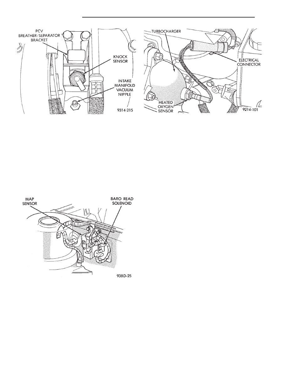
KNOCK SENSOR—PCM INPUT
The knock sensor generates a signal when spark
knock occurs in the combustion chambers. The sensor
can detect detonation in the cylinders. The sensor
provides information used by the PCM to modify
spark advance and boost schedules in order to elimi-
nate detonation.
The knock sensor is installed into the engine, be-
hind the PCV breather/separator (Fig. 11).
MANIFOLD ABSOLUTE PRESSURE (MAP)
SENSOR—PCM INPUT
The PCM supplies 5 volts to the MAP sensor. The
Map sensor converts intake manifold pressure into
voltage. The PCM monitors the MAP sensor output
voltage. As vacuum increases, MAP sensor voltage
decreases proportionately. Also, as vacuum decreases,
MAP sensor voltage increases proportionately.
Fig. 7 Coolant Temperature Sensor
Fig. 8 Crankshaft Position Sensor
Fig. 9 Timing Slots
Fig. 10 Crankshaft Position Sensor Location
Ä
FUEL SYSTEMS
14 - 87
During cranking, before the engine starts running,
the PCM determines atmospheric air pressure from
the MAP sensor voltage. While the engine operates,
the PCM determines intake manifold pressure and
barometric pressure from the MAP sensor voltage.
Based on MAP sensor voltage and inputs from other
sensors, the PCM adjusts spark advance, air/fuel
mixture and controls the turbocharger wastegate.
The MAP sensor (Fig. 12) mounts underhood on
the right side of the engine compartment. The sensor
connects electrically to the PCM.
HEATED OXYGEN SENSOR (O
2
SENSOR)—PCM
INPUT
The O
2
sensor is located in the turbocharger outlet
and provides an input voltage to the PCM (Fig. 13).
The input tells the PCM the oxygen content of the
exhaust gas. The PCM uses this information to fine
tune the air-fuel ratio by adjusting injector pulse
width.
The O
2
sensor produces voltages from 0 to 1 volt,
depending upon the oxygen content of the exhaust
gas in the exhaust manifold. When a large amount of
oxygen is present (caused by a lean air-fuel mixture),
the sensor produces a low voltage. When there is a
lesser amount present (rich air-fuel mixture) it pro-
duces a higher voltage. By monitoring the oxygen
content and converting it to electrical voltage, the
sensor acts as a rich-lean switch.
The oxygen sensor is equipped with a heating ele-
ment that keeps the sensor at proper operating tem-
perature during all operating modes. Maintaining
correct sensor temperature at all times allows the
system to enter into closed loop operation sooner.
Also, it allows the system to remain in closed loop
operation during periods of extended idle.
In Closed Loop operation the PCM monitors the O
2
sensor input (along with other inputs) and adjusts
the injector pulse width accordingly. During Open
Loop operation the PCM ignores the O
2
sensor input.
The PCM adjusts injector pulse width based on pre-
programmed (fixed) values and inputs from other
sensors.
SPEED CONTROL—PCM INPUT
The speed control system provides four separate
voltages (inputs) to the PCM. The voltages corre-
spond to the On/Off, Set, and Resume.
The speed control ON voltage informs the PCM
that the speed control system has been activated.
The speed control SET voltage informs the PCM that
a fixed vehicle speed has been selected. The speed
control RESUME voltage indicates the previous fixed
speed is requested. The speed control OFF voltage
tells the PCM that the speed control system has de-
activated. Refer to Group 8H for further speed con-
trol information.
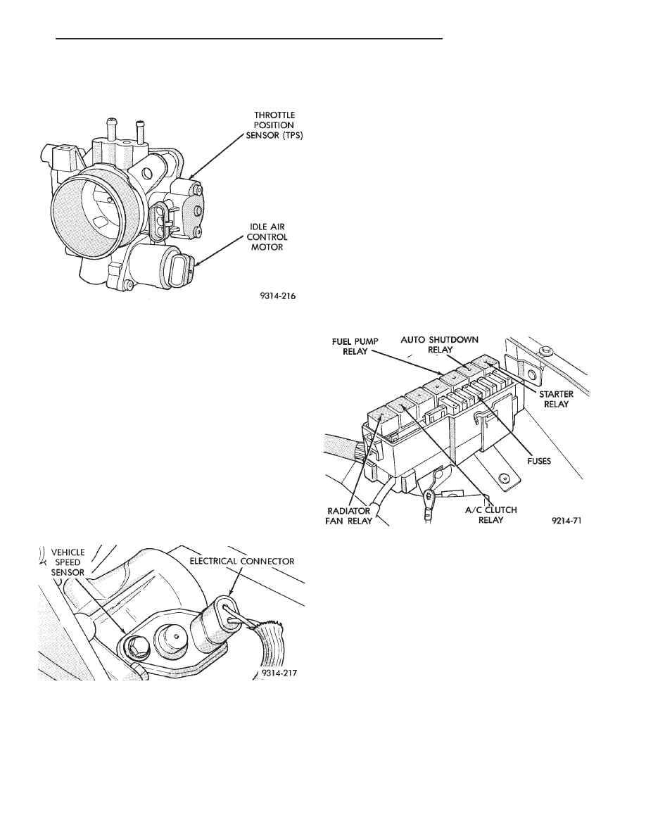
THROTTLE POSITION SENSOR (TPS)—PCM INPUT
The Throttle Position Sensor (TPS) is mounted on
the throttle body and connected to the throttle blade
shaft (Fig. 14). The TPS is a variable resistor that
provides the PCM with an input signal (voltage) rep-
Fig. 11 Knock Sensor
Fig. 12 MAP Sensor
Fig. 13 Heated Oxygen Sensor
14 - 88
FUEL SYSTEMS
Ä
resenting throttle blade position. As the position of
the throttle blade changes, the resistance of the TPS
changes.
The PCM supplies approximately 5 volts to the
TPS. The TPS output voltage (input signal to the
PCM) represents the throttle blade position. The TPS
output voltage to the PCM varies from approxi-
mately 0.5 volt at minimum throttle opening (idle) to
4 volts at wide open throttle. Along with inputs from
other sensors, the PCM uses the TPS input to deter-
mine current engine operating conditions and adjust
fuel injector pulse width and ignition timing.
VEHICLE SPEED SENSOR—PCM INPUT
The vehicle speed sensor (Fig. 15) is located on the
transaxle extension housing. The sensor input is
used by the PCM to determine vehicle speed and dis-
tance traveled.
The speed sensor generates 8 pulses per sensor rev-
olution. These signals, along with a closed throttle
signal from the TPS, determine if a closed throttle
deceleration
or
normal
idle
condition
(vehicle
stopped) exists. Under deceleration conditions, the
PCM adjusts the idle air control motor to maintain a
desired MAP value. Under idle conditions, the PCM
adjusts the idle air control motor to maintain desired
engine speed.
AIR CONDITIONING CLUTCH RELAY—PCM
OUTPUT
The PCM operates the air conditioning clutch relay
ground circuit. The radiator fan relay supplies bat-
tery power to the solenoid side of the A/C clutch re-
lay. The air conditioning clutch relay will not
energize unless the radiator fan relay energizes. The
PCM energizes the radiator fan relay when the air
conditioning or defrost switch is put in the ON posi-
tion and the low pressure and high pressure switches
close. When the PCM senses wide open throttle
through the throttle position sensor, or low engine
RPM it will de-energize the A/C clutch relay, open
it’s contacts and prevent air conditioning clutch en-
gagement.
On AG Body vehicles, the relay is located in the
power distribution center (Fig. 16).
GENERATOR FIELD—PCM OUTPUT
The PCM regulates the charging system voltage
within a range of 12.9 to 15.0 volts. Refer to Group
8A for charging system information.
AUTO SHUTDOWN (ASD) RELAY AND FUEL PUMP
RELAY—PCM OUTPUT
The PCM operates the auto shutdown (ASD) relay
and fuel pump relay through one ground path. The
PCM operates the relays by switching the ground
path on and off. Both relays turn on and off at the
same time.
The ASD relay connects battery voltage to the fuel
injector and ignition coil. The fuel pump relay con-
nects battery voltage to the fuel pump and oxygen
sensor heating element.
The PCM turns the ground path off when the igni-
tion switch is in the Off position. Both relays are off.
When the ignition switch is in the On or Crank po-
Fig. 14 Throttle Position Sensor and Idle Air Control
Motor
Fig. 15 Vehicle Speed Sensor
Fig. 16 Power Distribution Center—AG Body
Ä
FUEL SYSTEMS
14 - 89
Нет комментариевНе стесняйтесь поделиться с нами вашим ценным мнением.
Текст