Chrysler Le Baron, Dodge Dynasty, Plymouth Acclaim. Manual — part 181

HOOD ORNAMENT AY/P-S
REMOVAL (FIG. 2)
(1) Remove grille.
(2) Locate hood ornament spring under grille open-
ing panel header.
(3) Compress hood ornament spring enough to
clear hooks on end of retaining wire.
(4) Squeeze retainer wire hooks together and push
hooks inside spring.
(5) Rotate
spring
counterclockwise
to
separate
spring from retainer.
(6) Separate hood ornament from grille opening
panel.
INSTALLATION
Reverse the preceding operation.
GRILLE OPENING PANEL AY/P BODY
For service procedures for headlamp related compo-
nents refer to Group 8L, Lamps.
REMOVAL (FIG. 3)
(1) Remove front bumper and grille.
(2) Remove front end splash shields as necessary to
gain access to behind fenders.
(3) Remove nuts holding GOP mouldings to front
fenders.
(4) Remove nuts holding grille opening panel to
front fenders.
(6) Disconnect concealed headlamp motor wire con-
nector.
(7) Disconnect all lamp wire connectors.
(8) Remove bolts holding grille opening panel to
radiator closure panel and center brace.
(9) Separate grille opening panel from vehicle.
INSTALLATION
Reverse the preceding operation.
GRILLE OPENING PANEL AY/S BODY
For service procedures for headlamp related compo-
nents refer to Group 8L, Lamps.
REMOVAL (FIG. 4)
(1) Remove front bumper and grille.
(2) Remove front end splash shields as necessary to
gain access to behind fenders.
(3) Remove nuts holding mouldings to front fend-
ers.
(4) Remove bolts holding mouldings to bottom of
grille opening panel and separate mouldings from ve-
hicle.
(5) Remove nuts holding grille opening panel to
front fenders.
(6) Disconnect concealed headlamp motor wire con-
nector.
(7) Disconnect headlamp wire connectors.
(8) Remove bolts holding grille opening panel to
radiator closure panel mount brackets and center
brace.
(9) Separate grille opening panel from vehicle.
INSTALLATION
Reverse the preceding operation.
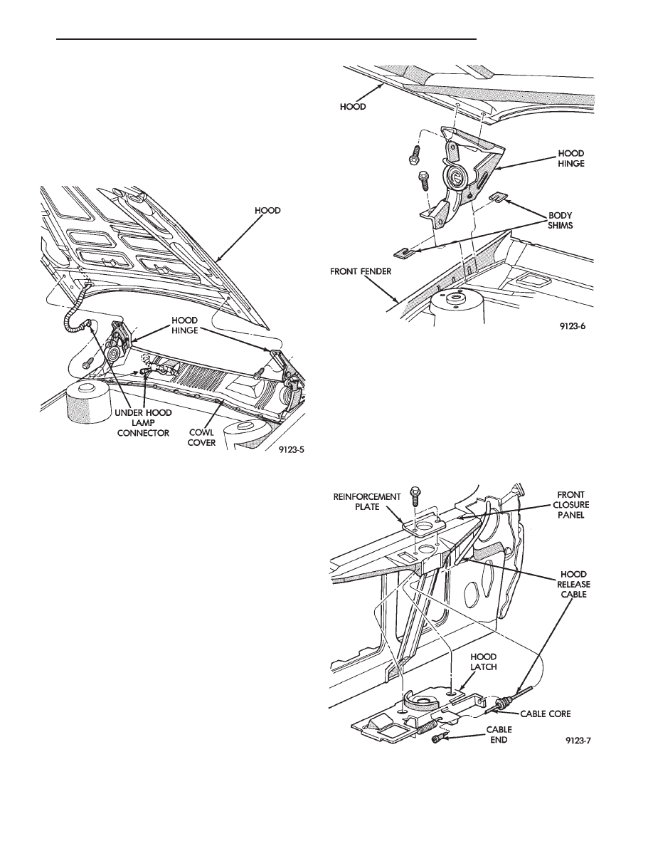
HOOD AND HINGES
HOOD REMOVAL (FIG. 5)
(1) Raise hood to full up position.
(2) Lift front edge of cowl cover on the right side of
the windshield washer bottle and disconnect the un-
der hood lamp wire connector.
(3) Mark all bolt and hinge attachment locations
with a grease pencil or other suitable device to pro-
vide reference marks for installation. When install-
ing hood, align all marks and secure bolts. The hood
should be aligned to 4 mm (0.160 in.) gap to the front
fenders and flush across the top surfaces along fend-
ers.
Fig. 3 Grille Opening Panel—AY/P Body
Fig. 4 Grille Opening Panel—AY/S Body
23 - 134
AY-BODY
Ä
(4) Remove the top hood to hinge bolts and loosen
the bottom bolts until they can be removed by hand.
(5) With assistance of a helper at the opposite side
of the vehicle to support the hood, remove the bottom
hood to hinge bolts. Separate the hood from the ve-
hicle.
HOOD INSTALLATION
Reverse the preceding operation.
HOOD HINGE REMOVAL (FIG. 6)
(1) Support hood on the side that requires hinge
replacement.
(2) Mark all bolt and hinge attachment locations
with a grease pencil or other suitable device to pro-
vide reference marks for installation. When install-
ing hood hinge, align all marks and secure bolts. The
hood should be aligned to 4 mm (0.160 in.) gap to the
front fenders and flush across the top surfaces along
fenders. Shims can be added or removed under hood
hinge to achieve proper hood height.
(3) Remove hood to hinge attaching bolts.
(4) Remove hood hinge to front fender attaching
bolts and separate hinge from vehicle.
HOOD HINGE INSTALLATION
Reverse the preceding operation. If necessary, paint
new hinge before installation.
HOOD LATCH AND RELEASE CABLE
HOOD LATCH REMOVAL (FIG. 7)
(1) Raise hood top the full up position.
(2) Remove hood latch attaching bolts holding
latch to radiator closure panel and separate from ve-
hicle.
(3) Pry release cable casing attachment from slot
receiver on latch, disengage cable end from latch arm
hook.
HOOD LATCH INSTALLATION
Reverse the preceding operation.
Fig. 5 Hood
Fig. 6 Hood Hinge—Typical
Fig. 7 Hood Latch Assembly—Typical
Ä
AY-BODY
23 - 135

HOOD LATCH RELEASE CABLE REMOVAL
(FIG. 8)
(1) Raise hood to the full up position.
(2) Remove push-in fasteners holding hood latch
cover to radiator closure panel and separate cover
from vehicle.
(3) Disconnect hood release cable casing and cable
end from hood latch assembly. Refer to Hood Latch
Removal procedure in this section.
(4) Remove hood latch release cable handle attach-
ing bolts from under left lower edge of instrument
panel.
(5) Disengage release cable rubber grommet from
engine compartment dash panel behind instrument
panel.
(6) Rout cable assembly through engine compart-
ment around battery, under fender lip, under relay
bank, and under wiring harnesses, toward dash
panel. Push cable through access hole in dash panel
under the brake master cylinder, into passenger com-
partment.
HOOD LATCH RELEASE CABLE
INSTALLATION
Reverse the preceding operation.
FRONT END SPLASH SHIELDS
FRONT WHEELHOUSE SPLASH SHIELD
REMOVAL (FIG. 9)
(1) Hoist vehicle and support on suitable safety
stands.
(2) Remove front wheel assembly.
(3) Remove push-in fasteners holding front wheel-
house splash shield to fender opening lip and inner
wheelhouse area.
(4) Separate wheelhouse splash shield from vehi-
cle.
FRONT WHEELHOUSE SPLASH SHIELD
INSTALLATION
Reverse the preceding operation.
TRANSAXLE SPLASH SHIELD REMOVAL (FIG.
9)
(1) Remove one front wheelhouse splash shield
push-in fastener and separate wheelhouse splash
shield from transaxle splash shield.
(2) Remove transaxle splash shield attaching bolts
and separate transaxle splash shield from vehicle.
TRANSAXLE SPLASH SHIELD INSTALLATION
Reverse the preceding operation.
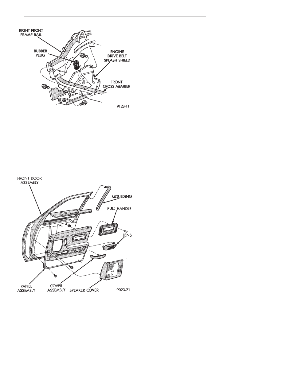
ENGINE DRIVE BELT SPLASH SHIELD
REMOVAL (FIG. 10)
(1) Hoist vehicle and support on suitable safety
stands.
(2) Remove bolts holding engine drive belt splash
shield to right frame rail.
(3) Separate drive belt splash shield from vehicle.
ENGINE DRIVE BELT SPLASH SHIELD
INSTALLATION
Reverse the preceding operation.
FRONT DOOR TRIM PANEL
TRIM PANEL REMOVAL (FIG. 11)
(1) Disengage frog-leg fasteners holding power seat
switch/speaker bezel to door trim. Separate bezel
from trim panel.
(2) Disconnect power seat switch wire connector.
(3) Remove screws holding trim panel to door from
around speaker and power seat switch.
(4) Remove screws holding pull handle to door trim
and separate pull handle from door.
(5) Remove hidden screws holding trim panel to in-
ner door panel from behind carpet insert.
Fig. 8 Hood Latch Release Cable—Typical
Fig. 9 Front Wheelhouse and Transaxle Splash
Shields
23 - 136
AY-BODY
Ä
(6) Disengage frog-leg fasteners holding trim panel
to inner door panel.
(7) Lift trim panel upward and separate trim from
door.
(8) Disconnect courtesy lamp, power door lock
switch and power window switch wire connectors.
TRIM PANEL INSTALLATION
Reverse the preceding operation.
SIDE VIEW MIRROR TRIM COVER
REMOVAL
(1) Remove Front door trim panel.
(2) Disconnect power mirror wire connector.
(3) Remove screws holding mirror trim cover to
door frame.
INSTALLATION
Reverse the preceding operation.
DOOR FRAME TRIM MOULDING
REMOVAL (FIG. 11)
(1) Remove front door trim panel.
(2) Disengage trim clips holding moulding to win-
dow opening frame and separate moulding from door.
INSTALLATION
Reverse the preceding operation.
FRONT DOOR SILENCER AND WATER SHIELD
REMOVAL
(1) Remove front door trim panel.
(2) Pull water shield from adhesive around perim-
eter of door inner panel.
INSTALLATION
Reverse the preceding operation.
FRONT DOOR AND HINGE
The front door hinge is welded to the door and
bolted to the hinge pillar. The door half of the hinge
pivots on a removable hinge pin. The hinge pin is
driven in from the bottom on the top hinge and from
the top on the bottom hinge. All adjustments to the
hinge are performed on the hinge pillar half of the
hinge. If the welded half of the hinge must be bent to
align door, consult an authorized body repair facility.
FRONT DOOR REMOVAL (FIG. 12)
(1) Remove door trim panel, silencer pad, and wa-
ter shield.
(2) Disconnect all wire connectors and wire har-
ness hold downs inside door and push wire harness
through access hole in front of door into hinge pillar
opening.
(3) Open door and support door on a suitable lift-
ing device.
(4) Drive bottom hinge pin upward and remove pin
from hinge.
(5) Drive top hinge pin downward and remove pin
from hinge.
FRONT DOOR INSTALLATION
Reverse the preceding operation. The door should
not require re-alignment. If door does need align-
ment, refer to Front Door Hinge Installation para-
graph in this section.
FRONT DOOR HINGE REMOVAL (FIG. 12)
(1) Remove front fender wheelhouse splash shield.
Refer to Front Wheelhouse Splash Shield Removal
paragraph in this section.
(2) Support door on a suitable lifting device.
(3) Drive out hinge pin on the effected hinge.
Fig. 10 Engine Drive Belt Splash Shield—Typical
Fig. 11 Front Door Trim Panel
Ä
AY-BODY
23 - 137
Нет комментариевНе стесняйтесь поделиться с нами вашим ценным мнением.
Текст