Chrysler Le Baron, Dodge Dynasty, Plymouth Acclaim. Manual — part 241
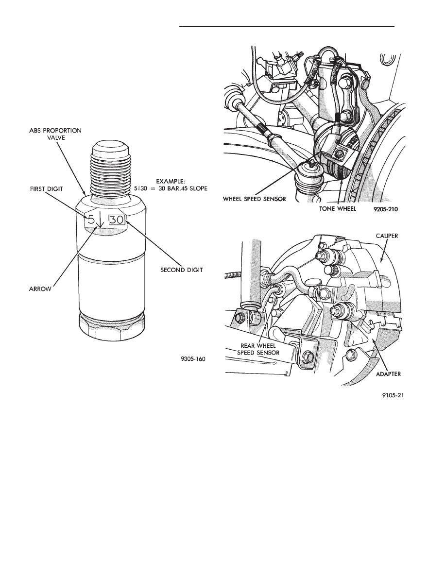
PROPORTIONING VALVES
Two Proportioning Valves (Fig. 3) are used in the
system, one for each rear brake hydraulic circuit.
The Proportioning Valves function the same as in a
standard brake system. The Proportioning Valves are
located on the bottom of the hydraulic assembly (Fig.
1). They are the same screw in type as the ones used
on the Bendix Anti-Lock 10 and Bosh Anti-Lock
Brake systems.
WHEEL SPEED SENSORS
One Wheel Speed Sensor (WSS), is located at each
wheel (Fig. 4 and 5), and sends a small (AC) signal
to the control module (CAB). This signal is generated
by magnetic induction. The magnetic induction is
created, when a toothed sensor ring Tone Wheel (Fig.
6) passes a stationary magnetic Wheel Speed Sensor.
The (CAB) converts the (AC) signal generated at
each wheel into a digital signal. If a wheel locking
tendency is detected, the (CAB) will then modulate
hydraulic pressure to prevent the wheel(s) from lock-
ing.
The front Wheel Speed Sensor is attached to a boss
in the steering knuckle (Fig. 4). The tone wheel is
part of the outboard constant velocity joint. The rear
Wheel Speed Sensor is mounted to the caliper adap-
tor (Fig. 5) and the rear tone wheel is an integral
part of the rear wheel hub (Fig. 6). The speed sensor
air gap is NOT adjustable.
The four Wheel Speed Sensors are serviced individ-
ually. The front Tone Wheels are serviced as an as-
sembly with the outboard constant velocity joint. The
rear Tone Wheels are serviced as an assembly with
the rear brake hub.
Correct Anti-Lock system operation is dependent
on the vehicle’s wheel speed signals, that are gener-
ated by the Wheel Speed Sensors. The vehicle’s
wheels and tires must all be the same size and type
to generate accurate signals. In addition, the tires
must be inflated to the recommended pressures for
optimum system operation. Variations in wheel and
tire size or significant variations in inflation pres-
sure can produce inaccurate wheel speed signals.
Fig. 3 Proportioning Valve Identification
Fig. 4 Front Wheel Speed Sensor
Fig. 5 Rear Wheel Speed Sensor
5 - 118
ANTI-LOCK 6 BRAKE SYSTEM
Ä
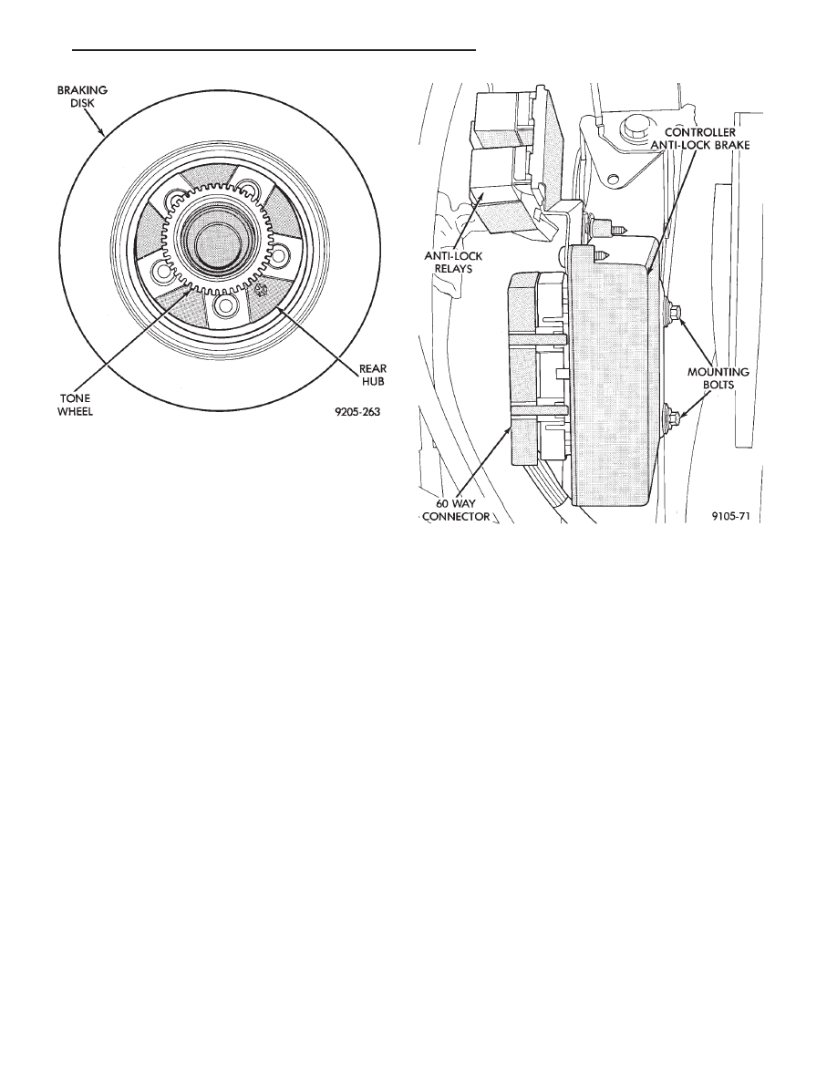
CONTROLLER ANTI-LOCK BRAKE (CAB)
The Anti-Lock Brake Controller is a small micro-
processor based device which monitors the brake sys-
tem and controls the system while it functions in
Anti-Lock mode. The CAB is mounted on the top of
the right front frame rail and uses a 60-way system
connector (Fig. 7). The power source for the CAB is
through the ignition switch in the Run or On posi-
tion. THE CONTROLLER ANTI-LOCK BRAKE
(CAB) IS NOT ON THE CCD BUS
The primary functions of the (CAB) are:
(1) Detect wheel locking tendencies.
(2) Control fluid modulation to the brakes while in
Anti-Lock mode.
(3) Monitor the system for proper operation.
(4) Provide communication to the DRB II while in
diagnostic mode.
The (CAB) continuously monitors the speed of each
wheel, through the signals generated at the Wheel
Speed Sensors, to determine if any wheel is begin-
ning to lock. When a front wheel locking tendency is
detected, the (CAB) will isolate the master cylinder
from the wheel brakes. This is done by activating the
Isolation Valves. The (CAB) then commands the ap-
propriate Build/Decay valves to modulate brake fluid
pressure in some or all of the hydraulic circuits. The
(CAB) continues to control pressure in individual hy-
draulic circuits until a locking tendency is no longer
present.
The (ABS) system is constantly monitored by the
(CAB) for proper operation. If the (CAB) detects a
fault, it will turn on the Amber Anti-Lock Warning
Lamp and disable the ABS braking system. The nor-
mal Non ABS braking system will remain opera-
tional.
The (CAB) contains a self-diagnostic program
which will turn on the Amber Anti-Lock Warning
Lamp when a system fault is detected. Faults are
stored in a diagnostic program memory. There are 16
fault codes which may be stored in the (CAB) and
displayed through the DRB II. These fault codes will
remain in the (CAB) memory even after the ignition
has been turned off. The fault codes can be cleared
by using the DRB II diagnostics tester, or they will
be automatically cleared from the memory after (50)
ignition switch on/off cycles.
CONTROLLER ANTI-LOCK BRAKE (INPUTS)
• Four wheel speed sensors.
• Stop lamp switch.
• Ignition switch.
• System relay voltage.
• Ground.
• Pump/Motor Relay Monitor
• Diagnostics Communications
CONTROLLER ANTI-LOCK BRAKE (OUTPUTS)
• 6 modulator valves, 4 Build/Decay and 2 isolation
valves.
• Anti-Lock warning lamp.
• System relay actuation.
• Diagnostic communication.
• Pump motor relay actuation
Fig. 6 Tone Wheel (Typical)
Fig. 7 Location Controller Anti-Lock Brake (CAB)
Ä
ANTI-LOCK 6 BRAKE SYSTEM
5 - 119
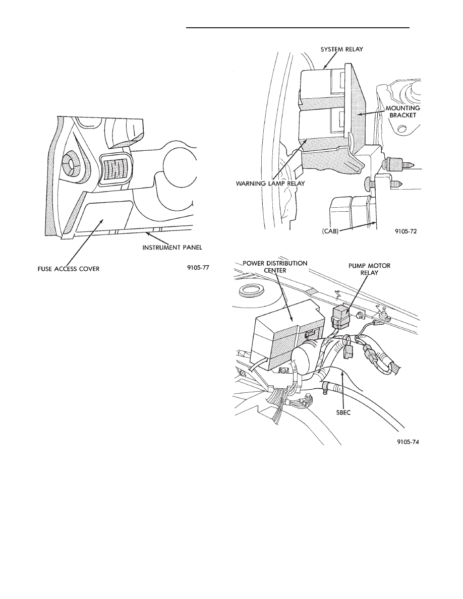
DIAGNOSTIC CONNECTOR
On the AA, AG, AJ and AP bodies, the Bendix An-
ti-Lock System diagnostic connector is located under
the fuse panel access cover. The access cover is lo-
cated on the lower section of the instrument panel on
the left side of the steering column. The diagnostics
connector is a blue 6 way connector see (Fig. 8).
ANTI-LOCK SYSTEM RELAYS AND WARNING
LAMPS
SYSTEM RELAY
The (ABS) Modulator Valves and Anti-Lock Warn-
ing Lamp Relay. Are powered through a System Re-
lay located on a bracket mounted to the (CAB) see
(Fig. 9) for location of the relay. The System Relay
provides power to the (CAB) for modulator valve op-
eration (pins 47 and 41) after the startup cycle when
the ignition is turned on.
ANTI-LOCK WARNING LAMP RELAY
The Amber Anti-Lock Warning Lamp is controlled
by the Anti-Lock Warning Lamp relay. The relay is
mounted to the same bracket as the system relay at
the (CAB) see (Fig. 9). With the relay de-energized,
the lamp is lit. When the System Relay is energized
by the (CAB), the Anti-Lock warning lamp relay is
energized, and the lamp is turned off. Thus, the lamp
will be lit if the (CAB) is disconnected or if a system
fault causes the (ABS) function to be turned off.
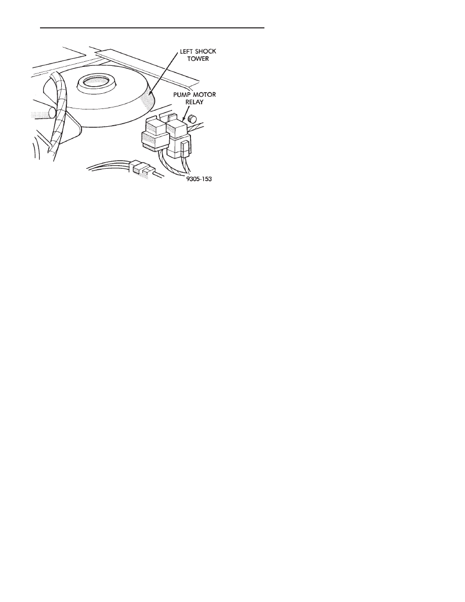
PUMP/MOTOR RELAY
Pump/Motor power is supplied by the Pump/Motor
Relay. The Pump/Motor Relay is either mounted on
the left front inner fender shield, or the front of the
left shock tower. The mounting location is dependent
on whether the vehicle is or is not equipped with a
power distribution center. See (Fig. 10 and 11) for
specific mounting locations.
ANTI-LOCK WARNING LAMP OFF
System Relay and Anti-Lock Warning Lamp
Relay Energized
From pin 57 the (CAB) energizes the system relay
coil. The electrical current flow in the coil closes the
system relay. Then electrical current is provided to
pins 47 and 41 of the (CAB) to provide power to the
modulator valves. This electrical current also ener-
gizes the Amber Anti-Lock Warning Lamp Relay
coil. The current flow in the Anti-Lock Warning
Fig. 8 A.B.S. Diagnostic Connector Location
Fig. 9 System Relay/Warning Lamp Relay
Fig. 10 Pump Motor Relay With Power Distribution
Center
5 - 120
ANTI-LOCK 6 BRAKE SYSTEM
Ä
Lamp Relay opens the Anti-Lock Warning Lamp Re-
lay switch. This breaks the ground path to the Am-
ber Anti-Lock Warning Lamp and the light is turned
off.
The (CAB) by itself, also has the ability to turn on
the Amber Anti-Lock Warning Lamp. The (CAB) can
turn on the Amber Anti-Lock Warning Lamp by pro-
viding a ground at pin 15.
ANTI-LOCK WARNING LAMP ON
System Relay and Anti-Lock Warning Lamp
Relay De-Energized.
When the Amber Anti-Lock Warning Lamp is on,
there is no electrical current flow from the (CAB) at
pin 57. The System Relay coil is NOT energized. No
electrical current flows to pin 47 and 41 (modulator
valve power), or to the Anti-Lock Warning Lamp Re-
lay coil. Thus, the Amber Anti-Lock Warning Lamp
is not energized. The Amber Anti-Lock Warning
Lamp is grounded through the Anti-Lock Warning
Lamp Relay contacts. The Amber Anti-Lock Warning
Lamp is turned on.
HYDRAULIC CIRCUITS AND VALVE OPERATION
Through the following operation descriptions and
diagrams. The function of the various hydraulic con-
trol valves in the ABS system will be described. The
fluid control valves mentioned below, control the flow
of pressurized brake fluid to the wheel brakes during
the different modes of Anti-Lock braking.
For explanation purposes we will assume all speed
sensors are sending the same wheel speed informa-
tion, requiring the same hydraulic fluid modulation
at the same rate.
NORMAL BRAKING
ISOLATION VALVES
Open to primary and secondary master cylinder
fluid supply (Fig. 1)
BUILD/DECAY VALVES
Closed (Fig. 1)
The brake pedal is applied. The travel of the brake
pedal closes primary and secondary circuits from the
master cylinder fluid supply. Brake fluid from the
primary and secondary circuits flows through the
open isolation valves, through the build/decay valves
to the wheel brakes.
ABS BRAKING-BUILD PRESSURE
ISOLATION VALVES
Closed, isolating wheel brakes from master cylin-
der primary and secondary fluid supply. Through
open build valves (Fig. 2).
BUILD/DECAY VALVES
Open (Fig. 2)
Fig. 11 Pump Motor Relay W/O Power Distribution
Center
Ä
ANTI-LOCK 6 BRAKE SYSTEM
5 - 121
Нет комментариевНе стесняйтесь поделиться с нами вашим ценным мнением.
Текст