Chrysler Le Baron, Dodge Dynasty, Plymouth Acclaim. Manual — part 349
(1) Be sure that the module has a battery feed
from the 20 Amp breaker in cavity 1 of the black
connector. Also affected would be the optical horn
and the stop lamps.
(2) Be sure that the module has an ignition feed
from 5 Amp fuse in cavity 8 of the black connector.
Also affected would be the body computer, instru-
ment cluster and message center.
(3) Be sure that the module has a ground from the
right side cowl behind the body computer to the cav-
ity 5 of the black connector.
(4) Be sure that you are supplying a good ground
to the programming wire.
(5) If the above circuits are good, replace the Re-
ceiver Module.
CONDITION: Doors can be locked or unlocked with
the Keyless Entry transmitter. But the doors will not
lock. The Vehicle Theft Alarm system will not arm,
when using only the power door LOCK switch in the
driver’s door.
(1) Be sure you have not left key in the ignition
column lock cylinder.
(2) If step 1 is OK, check the Key in Lock switch
circuit in the steering column for a short to ground.
(3) In this problem the body computer controls the
LOCK function. Be sure that it is providing a battery
voltage output to the door lock relay. The door lock
relay controls the door lock motors.
CONDITION: Doors will lock but Vehicle Theft
System will not arm when using the transmitter.
(1) The Keyless Entry Receiver Module controls
the door lock signal to the door lock relay. The door
lock relay controls the door lock motors. Check for
battery voltage at cavity 10 of the Theft Alarm mod-
ule from the Receiver module.
(2) If voltage is OK, replace Receiver module.
CONDITION: All doors except driver’s door will
lock with the transmitter.
(1) Test the driver’s door output of the Receiver
Module for a ground.
(2) If there is no ground at the pin, replace the Re-
ceiver module.
(3) If there is a ground at the output, replace the
door lock motor.
CONDITION: Only driver’s door will lock with the
transmitter.
• Repair ground circuit to unlock relay
• Replace unlock relay
CONDITION: Doors do not lock with the transmit-
ter, but still get horn CHIRP that indicates that they
did lock. Replace Receiver module.
CONDITION: Doors will lock with the transmitter
but there is no horn CHIRP.
(1) Press horn button, listen horn sound.
(2) If the horn sounded, change horn relay.
(3) Still no CHIRP, check continuity between the
horn relay and the receiver output pin. Repair as
necessary.
(4) Still no horn CHIRP, replace the receiver mod-
ule.
(5) If using a DRB II, refer to Body Diagnostic Pro-
cedures.
REMOTE KEYLESS MODULE REPLACEMENT
(1) Remove lower right instrument panel silencer.
(2) Remove glove box assembly.
(3) Remove three screws attaching the mounting
bracket to instrument panel.
(4) Lower bracket and module assembly, to discon-
nect wire connector.
(5) Remove two screws attaching the Remote Key-
less entry Module to bracket.
(6) Remove two screws attaching the security mod-
ule to bracket.
(7) To installation reverse above procedures.
LAMP OUTAGE MODULE REPLACEMENT
(1) Remove lower right instrument panel silencer.
(2) Remove glove box and ash receiver module.
(3) Remove three screws attaching the mounting
bracket to instrument panel.
(4) Lower bracket and module assembly, to discon-
nect wire connectors.
(5) Remove two screws attaching the Lamp Outage
Module to bracket.
(6) Remove two screws attaching the security mod-
ule to bracket.
(7) To installation reverse above procedures.
DOOR LOCK INHIBIT
The power door lock inhibit system prevents the
doors from being locked using the power door locks
when either of two conditions occur:
(1) The key is in the ignition switch and any of the
doors are open. The ignition switch does not have to
be ON.
(2) The key is in the ignition switch and the head-
lamp are on.
AC, AG, AJ AND AY BODIES
With the ignition switch in the ON or OFF position
and the driver’s door open the Body Controller will
ignore the command to lock the power door locks.
Once the key is removed, or the driver’s door is
closed, the Body Controller will allow the power door
locks to lock. Refer to Body Diagnostic Procedure
Manual for further testing procedures.
8P - 6
POWER LOCKS
Ä
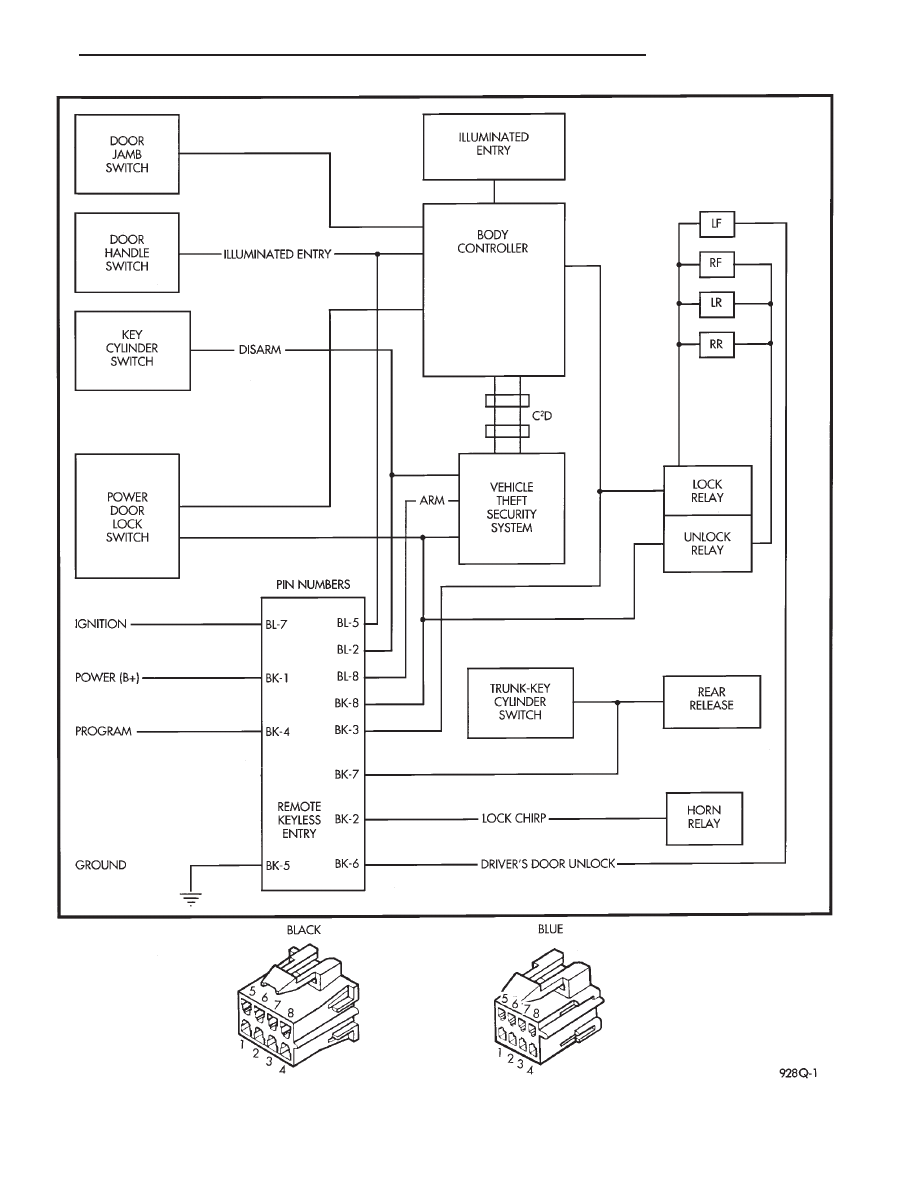
Fig. 12 Block Wiring Diagram
Ä
POWER LOCKS
8P - 7
AA BODY
Uses a power door lock inhibit relay. The relay is
located above the glove box compartment.
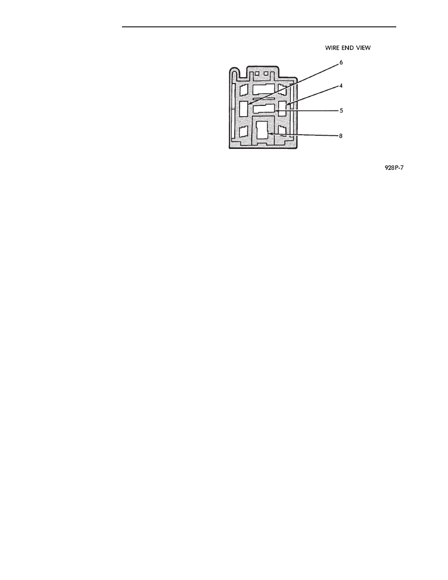
INHIBIT RELAY
(1) Using a voltmeter, test for battery voltage at
pin 4. If no voltage check fuse 15 (Fig. 13).
(2) Using a ohmmeter, check for continuity to
ground at pin 8. If no continuity to ground, check in-
strument panel ground.
(3) To check pin 5:
(a) The key is in the ignition switch and a door
is open.
(b) The key is in the ignition switch and the
headlamps are ON.
(c) Test for continuity to ground.
(d) If not, the relay contact is open or the relay is
being energized when it should not be. Pin 5 feeds
the ground from the relay to door lock switch.
(4) To check pin 6:
(a) The key is in the ignition switch and a door
is open.
(b) The key is in the ignition switch and the
headlamps are ON.
(c) Test for continuity to ground.
(d) If not, check key in switch, headlamps on
switch and/or door jamb switches. Pin 6, feeds
ground from key in switch to the relay.
Fig. 13 Inhibit Relay Connector
8P - 8
POWER LOCKS
Ä
VEHICLE THEFT SECURITY SYSTEM
CONTENTS
page
page
GENERAL INFORMATION . . . . . . . . . . . . . . . . . . 1
SECURITY SYSTEM DOOR SWITCH
REPLACEMENT
. . . . . . . . . . . . . . . . . . . . . . . . 2
SECURITY SYSTEM HOOD SWITCH
REPLACEMENT
. . . . . . . . . . . . . . . . . . . . . . . . 2
SYSTEM SELF-TESTS
. . . . . . . . . . . . . . . . . . . . 1
VEHICLE THEFT SECURITY SYSTEM MODULE
REPLACEMENT
. . . . . . . . . . . . . . . . . . . . . . . . 2
WHAT WILL TRIGGER THE SYSTEM
. . . . . . . . 1
GENERAL INFORMATION
JUMP-STARTING,
VEHICLE
EQUIPPED
WITH THEFT SECURITY SYSTEM. After the
booster battery has been connected, the Theft System
must be turned OFF. Using the key, lock then un-
lock either front door. This turns the Theft System
OFF and the remainder of the Jump-Starting proce-
dure can be followed.
If this procedure is not followed, the Theft System
electronics will prevent the engine from starting.
If a new Powertrain Control Module is installed,
the engine has to be cranked 20 times before the
alarm system activated.
This passive system is designed to protect against
whole vehicle theft. The system monitors vehicle
doors, hood, trunk key cylinder, and ignition action
for unauthorized operation. The alarm activates by
sounding the horn, flashing the park and tail lamps,
and providing an engine kill feature (Fig. 1).
Passive arming occurs upon normal vehicle exit,
open door, lock with power locks, close door. The SET
lamp in the panel will flash for 15 seconds, indicat-
ing that arming is in progress. If no monitored sys-
tems are activated during this period, the system
will arm. If the hood or trunk key cylinder switches
are not sensed by the system. The SET lamp will re-
main lit during the arming process, although the sys-
tem will still arm. The system is to be considered as
an active armed system when using the Remote Key-
less Entry. If the SET lamp does not illuminate at all
upon door closing it indicates that the system is not
arming.
Passive disarming occurs upon normal vehicle en-
try unlocking either door with the key, or unlocking
using the Remote Keyless transmitter. This disarm-
ing will also halt the alarm once it has been acti-
vated.
Whenever the battery is disconnected and recon-
nected, the Vehicle Theft Security System enters
power up alarm mode which flashes the park and tail
lamps and prevents the engine from running. To exit
this mode, the system must be disarmed as men-
tioned above.
A tamper alert exists to notify the driver that the
alarm had been activated, and the alarm has since
timed-out for more than 18 minutes. This alert con-
sists of 3 horn pulses when the vehicle is disarmed.
The alarm system will not arm if the doors are
manually locked, providing a manual override of the
alarm.
WHAT WILL TRIGGER THE SYSTEM
One of the following actions will trigger the system
while it is armed. Without properly disarming sys-
tem, by using the key or the remote transmitter.
(1) Opening the HOOD.
(2) Opening any DOOR.
(3) Removing the TRUNK KEY CYLINDER.
(4) Turning the IGNITION ON.
(5) The ignition switch can be turned to the acces-
sory position without triggering alarm system.
SYSTEM SELF-TESTS
A diagnostics mode is available in the system to
verify operation of all monitored switches or circuits.
To enter diagnostics, cycle the ignition key to the ac-
cessory position 3 times, leaving the key in this po-
sition.
Upon entering diagnostics, the park and tail lamps
will begin flashing to verify their operation. In addi-
tion, the horn will sound twice to indicate that the
trunk key cylinder is in its proper position. Return-
ing the ignition to the OFF position will stop the
lamps from flashing while keeping the system in di-
agnostics.
While in diagnostics mode, a horn pulse should oc-
cur at each of the following events indicating proper
operation:
(1) Beginning with all doors closed, open then close
each door. The horn will sound when the door ajar
switch closes, and then again when the switch opens.
There must be a 1 second delay between closing and
opening the switch.
(2) Open, then close the hood. The horn will sound
when the hood is opened, and again when it is closed.
Ä
VEHICLE THEFT SECURITY SYSTEM
8Q - 1
Нет комментариевНе стесняйтесь поделиться с нами вашим ценным мнением.
Текст