Chrysler Le Baron, Dodge Dynasty, Plymouth Acclaim. Manual — part 348
ELECTRIC MOTOR TEST
Make certain battery is in normal charged condi-
tion before circuits are tested.
To determine which motor is faulty, check each in-
dividual door for electrical lock and unlock or discon-
nect the motor connectors one at a time, while
operating the door lock switch. In the event that
none of the motors work, the problem maybe caused
by a shorted motor, or a bad switch. Disconnecting
the defective motor will allow the others to work.
The power lock motors are also equipped with a
thermal protection system which prevents the motors
from burning out. The motors may chatter if they are
continuously activated.
To test an individual door lock motor, disconnect
the wire connector at the motor (Fig. 2 and 3). Test
at the connector for 12 volts while applying door lock
switch. If no voltage repair wire. Apply 12 volts to
the motor terminal, and a known good ground to the
other terminal to check motor operation.
Should the motor defect be a result of a broken
wire, it should have no effect on the operation of the
other motors.
POWER DOOR LOCKS
When AC, AG, AJ or AY Body vehicles are
equipped with power door locks, the system includes
an automatic door locking feature which is actuated
through the vehicle’s body controller.
When this system is enabled the automatic door
locks will work automatically. When the system is
disabled the door locks will work by use of the door
lock switches only.
The body controller controls the power locks when
the door lock switch is activated. If the door lock
switch is pressed for longer than eight consecutive
seconds, the body controller will de-energize the door
lock relay. Also, the body controller will automati-
cally lock all doors when all of the conditions below
are met:
• All doors are closed
• The vehicle speed exceeds 15 6 1 MPH
• The throttle position sensor tip-in is greater than
10
6 2 degrees
The DRB II must be used to enable/disable the au-
tomatic door lock system. Refer to the Body Diagnos-
tic Procedures Manual for the procedure.
The body controller will automatically re-lock all
doors if the above conditions are met and if any of
the doors become ajar. The body controller does not
control the door unlock function. The switch is wired
directly to the lock relay.
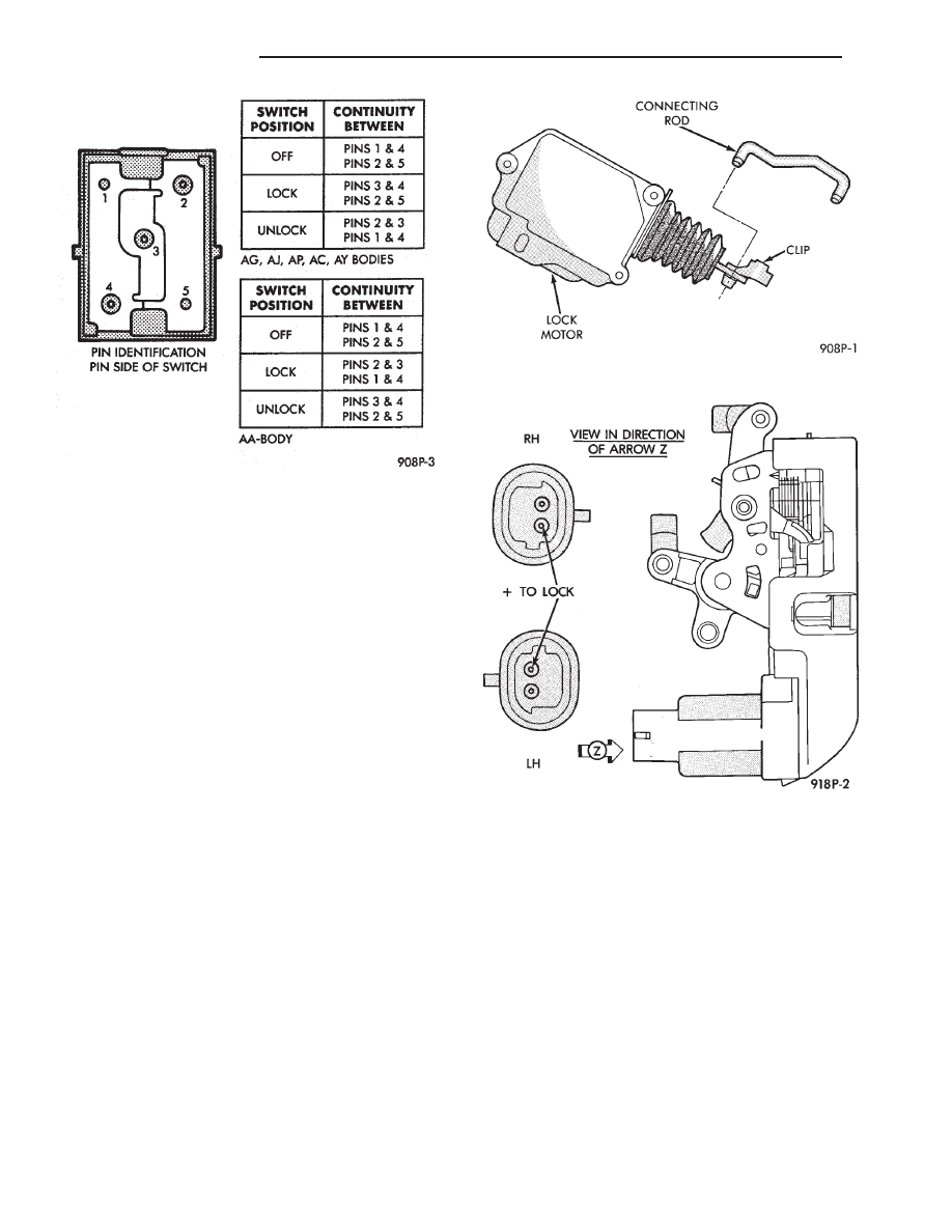
Fig. 1 Door Lock Switch Continuity
Fig. 2 Door Lock Motor
Fig. 3 Door Latch with Lock Motor—AC and AY
Bodies
8P - 2
POWER LOCKS
Ä
DOOR LOCK SYSTEM TEST
For complete testing of the AC, AG, AJ and AY
body automatic door lock systems, refer to the Body
Diagnostic Procedures Manual.
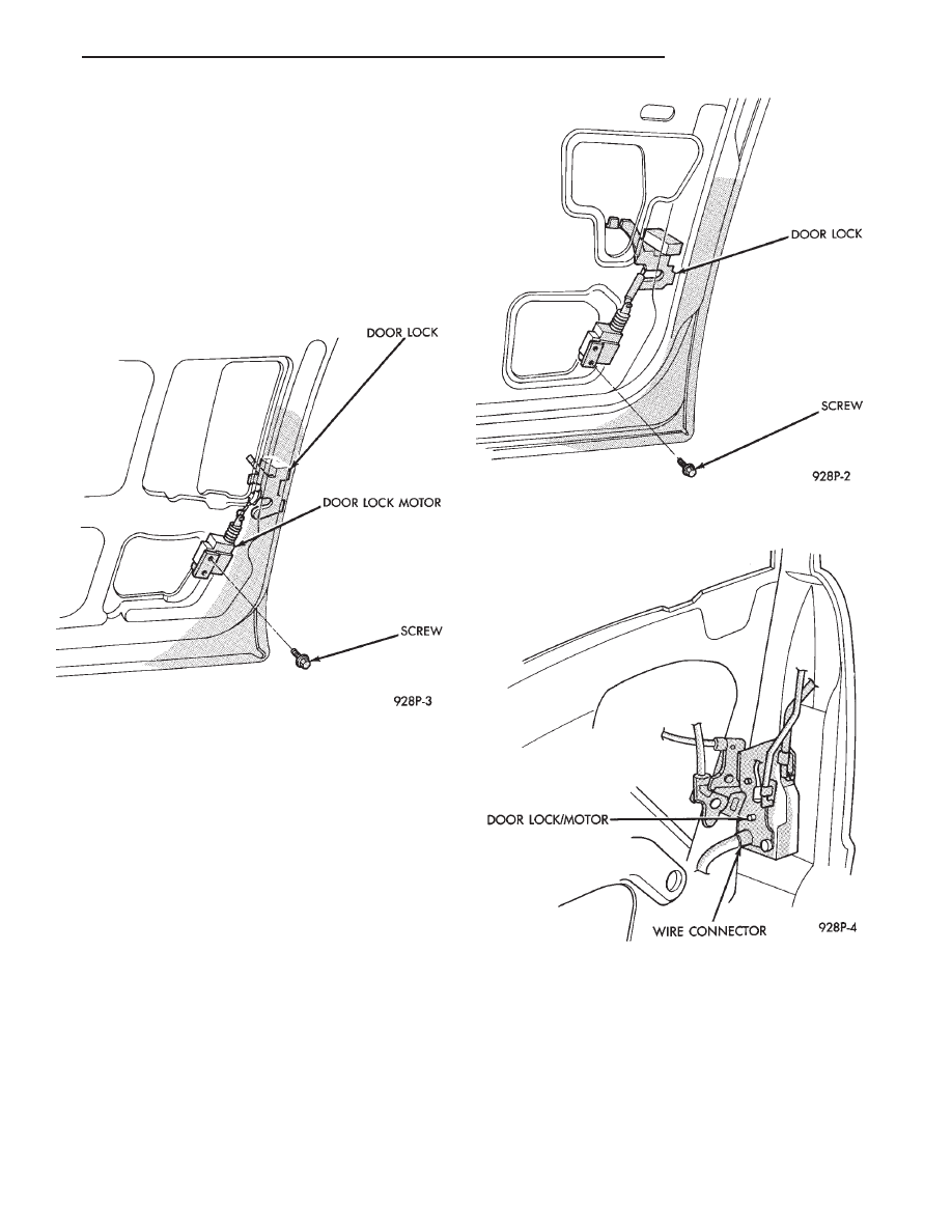
DOOR LOCK MOTOR REPLACEMENT
(1) Remove inside door release handle, window
regulator handle, if equipped and door trim panel.
(2) Roll door watershield away from lower rear cor-
ner of door to reveal inside panel access opening.
(3) Disconnect link at the motor as required (Fig. 4
through 7).
(4) Disconnect motor lead wires.
(5) Remove motor or latch attaching screws and re-
move motor assembly.
(6) For installation reverse above procedures.
DECK LID OPERATION
For vehicles equipped with electric deck lid release.
TEST
(1) Confirm solenoid lead wire is connected and 10
volts or more are available at solenoid.
(2) Provide proper ground through latch mounting
screws.
(3) Remove latch and examine plunger. Plunger
should spring back when pressed.
(4) Insure that solenoid plunger travel is adequate
approximately 16 mm (5/8 inch).
ADJUSTMENT
Adjust deck lid latch and striker so that deck lid
latches with a moderate slam. With ignition switch
in On or Accessory position, push deck lid unlock
switch. Should latch fail to lock or unlock replace
latch assembly.
DECK LID PULL-DOWN SYSTEM—AC and AY
BODIES
C-body vehicles have, as an option, a deck lid
power pull-down mechanism which latches and pulls
the deck lid down the last 25 mm (1 in.) of travel.
The system incorporates a combination latch/deck lid
Fig. 4 Front Power Door Lock Motors—AA, AG, AJ
and AP Bodies
Fig. 5 Rear Power Door Lock Motors—AA and AP
Bodies
Fig. 6 Front Power Door Lock Motors—AC and AY
Bodies
Ä
POWER LOCKS
8P - 3

release mechanism and a power pull-down motor as-
sembly (Fig. 8 through 10).
When the deck lid is closed, very light pressure is
required to cause the latch to grab the pull down bar.
The pull down motor will automatically take the
deck lid to its completely closed position.
POWER PULL DOWN
(1) Latch testing:
(a) With the deck lid open and the latch switch
released. There should be continuity between the
black with the red tracer (BK/RD*) and the black
(BK) wire (Fig. 10).
(b) With the latch switch depressed (as if the
deck lid was closed), there should be continuity be-
tween the black (BK) and the black with white
tracer (BK/WT*) wire terminals.
(c) If these results are not obtained, replace the
pull down latch.
(2) Pull down motor testing:
(a) With the pull down motor connector wiring
removed, connect a 12 volt positive source to the
red (RD) wire terminal of the motor and ground
the tan (TN) wire terminal. This will cause the
pull down bar to retract.
(b) With the positive source still connected to the
red (RD) wire terminal, ground the grey (GY) wire
terminal. This will cause the pull down bar to raise
Fig. 7 Rear Power Door Lock Motors—AC and AY
Bodies
Fig. 8 Deck Lid Pull Down Latch—AC and AY
Bodies
Fig. 9 Deck Lid Power Pull Down Motor—AC and AY
Bodies
Fig. 10 Deck Lid Power Pull Down Assembly—AC
and AY Bodies
8P - 4
POWER LOCKS
Ä
to the deck lid open position. If the pull down limit
switch is depressed at this time, the motor should
stop.
(c) If these results are not obtained, replace the
pull down motor assembly.
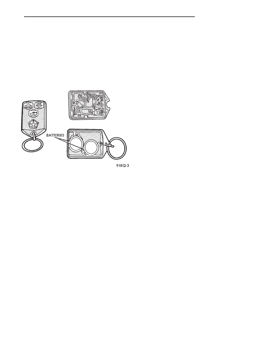
REMOTE KEYLESS ENTRY
OPERATION
The transmitter has three buttons for operation
(Fig. 11).
• UNLOCK driver’s door, enable illuminated entry,
and disarm the Theft Security System. Pushing and
releasing the button once will unlock the driver’s
door. Two times within five seconds all doors will un-
lock.
• LOCK all doors, set Theft Security System and
chirp horn. Chirp of horn is a short toot to notify
that the alarm system is set and the indicator lamp
on the instrument panel will flash for about 15 sec-
onds.
• Unlock Trunk Lid
• The receiver is capable of retaining VAC even
when power is removed.
• Each receiver must have at least one and no more
than two transmitters.
CONTROL RANGE
Operation range is within 7 meters (23 ft.) of the
receiver.
TRANSMITTER BATTERY
The battery can be removed without special tools
and are readily available at local retail stores. The
recommended battery is Duracell DL 2016 or equiv-
alent. Battery life is about one to two years.
PROGRAM REMOTE KEYLESS ENTRY
(1) Remove trim cover or floor console as needed
that may be covering the Air Bag System Diagnostic
Module (ASDM).
(2) Pull floor carpeting back between the accelera-
tor peddle and ASDM.
(3) Locate program line a dark green wire with a
insulator on the end. Located between the accelerator
and (ASDM).
(4) Turn ignition switch to the ON position.
(5) Connect the program line from the Remote
Keyless Entry Module to ground. The door locks will
lock and unlock to indicate the receiver is ready to
receive transmitter code. Trunk solenoid will not cy-
cle.
(6) Press any button on the transmitter to set code.
If there is a second transmitter it has to be set at
this time. The locks will cycle to confirm program-
ming.
(7) Disconnect the program line from ground. This
returns the system to its normal operation mode.
(8) Replace trim cover or floor console as neces-
sary.
HORN CHIRP CANCELLATION
During the programming operation the horn chirp
can be disabled using the following procedures:
(1) Remove trim cover or floor console as needed
that may be covering the Air Bag System Diagnostic
Module (ASDM).
(2) Pull floor carpeting back between the accelera-
tor peddle and ASDM.
(3) Locate program line a dark green wire with a
insulator on the end. Located between the accelerator
and (ASDM).
(4) Turn ignition switch ON.
(5) Connect the program line from the Remote
Keyless Entry Module to ground. The door locks will
lock and unlock to indicate the receiver is ready to
receive transmitter code. Trunk solenoid will not cy-
cle.
(6) Press any button on the transmitter to set code.
If there is a second transmitter it has to be set at
this time. The locks will cycle to confirm program-
ming.
(7) Press LOCK then UNLOCK transmitter but-
tons repeat three times.
(8) Door locks and rear release will cycle three
times as feedback of Horn Chirp lockout.
(9) Remove ground from program line to restore
normal system operation.
(10) To reinstate the Horn Chirp feature refer to
Program Remote Keyless Entry.
TESTING
CONDITION: When trying to program the receiver
module in the vehicle with a new transmitter and
there is no response from the module, Example: the
door locks do not cycle through a lock/unlock routine.
Refer to Fig. 12 for a block wiring diagram or to
Group 8W, Wiring Diagrams.
Fig. 11 Transmitter
Ä
POWER LOCKS
8P - 5
Нет комментариевНе стесняйтесь поделиться с нами вашим ценным мнением.
Текст