Chrysler Le Baron, Dodge Dynasty, Plymouth Acclaim. Manual — part 18
AY-VEHICLE REAR BUMPER
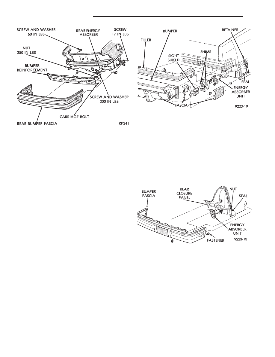
REAR BUMPER REMOVAL—AY/P-BODY (FIG.
21)
(1) Remove nuts holding fascia to quarter panel
ends.
(2) Support bumper assembly on suitable lifting
device and remove bolts holding bumper reinforce-
ment to energy absorber units.
(3) Separate bumper from vehicle.
INSTALLATION
Reverse the preceding operation. Align bumper
height to fit flush to bottom of tail lamp.
REAR BUMPER OVERHAUL—AY/P-BODY
(1) Position bumper assembly on a suitable padded
work surface to avoid damage to painted fascia.
(2) Remove bolts holding bumper face bar to rein-
forcement and separate face bar from assembly.
(3) Remove push-in fasteners holding fascia to re-
inforcement.
(4) Remove upper reinforcement to fascia attaching
bolts and separate reinforcement from fascia.
REAR BUMPER ASSEMBLY
Reverse the preceding operation.
REAR BUMPER REMOVAL—AY/S-BODY (FIG.
22)
(1) In luggage compartment, separate liners from
quarter panels to gain access to fascia nuts.
(2) Remove nuts holding bumper fascia to quarter
panels.
(3) Remove fasteners holding bumper fascia to
wheel opening flange.
(4) Disconnect license plate lamp wire connectors.
(5) Remove bolts holding bumper to rear closure
panel.
(6) Remove nuts holding bumper to energy ab-
sorber units.
(7) Separate bumper from vehicle.
INSTALLATION
Reverse the preceding operation.
Fig. 20 Rear Bumper—AP-Vehicle
Fig. 21 Rear Bumper—AY/P-Body
Fig. 22 Rear Bumper—AY/S-Body
13 - 8
FRAME AND BUMPERS
Ä
FRAME
INDEX
page
page
Crossmember
. . . . . . . . . . . . . . . . . . . . . . . . . . . 17
Frame Dimensions
. . . . . . . . . . . . . . . . . . . . . . . . 9
General Information
. . . . . . . . . . . . . . . . . . . . . . . . 9
GENERAL INFORMATION
In this section, references are made to Vehicle
Family (Body) codes. To determine the vehicle family
identification code, refer to the Introduction Group at
the front of this manual.
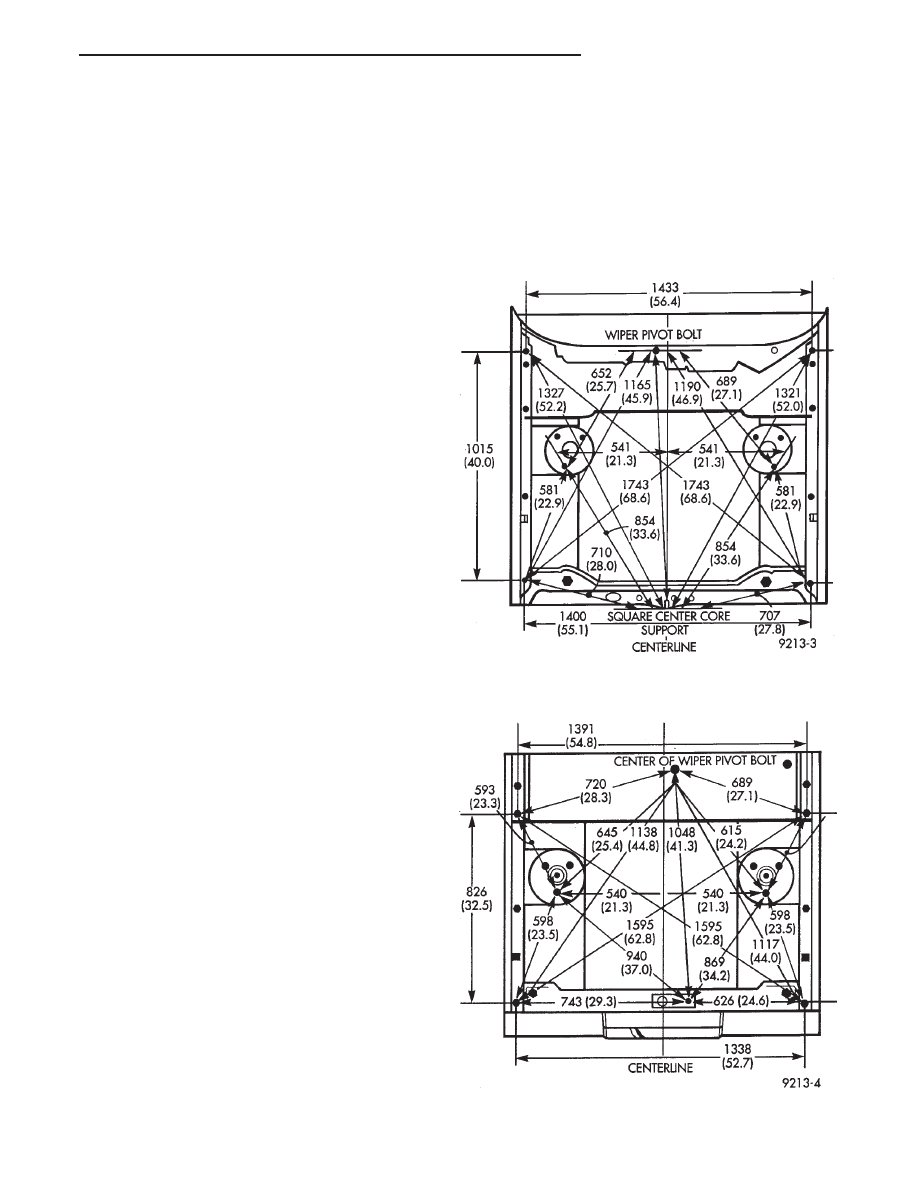
FRAME DIMENSIONS
Frame dimensions are listed in metric scale then
converted to inch scale listed in parenthesis. Engine
compartment charts include front suspension upper
strut damper mounting tower location. All dimen-
sions are from center to center of Principal Locating
Point (PLP), or from center to center of PLP and fas-
tener location.
VEHICLE PREPARATION
Position the vehicle on a level work surface. Using
screw or bottle jacks, adjust the vehicle height to the
specified PLP dimension above the Datum Line
(work surface). Vertical dimensions can be taken
from the datum line to the PLP.
ENGINE COMPARTMENT DIMENSIONS
Refer to Fig. 1, 2, 3, 4 or 5.
FRONT FRAME DIMENSIONS
Refer to Fig. 6
REAR FRAME DIMENSIONS
Refer to Fig. 7, 8, 9, 10 or 11.
Fig. 1 Engine Compartment Dimensions—AA-Body
Fig. 2 Engine Compartment Dimensions—AC-Body
Ä
FRAME AND BUMPERS
13 - 9
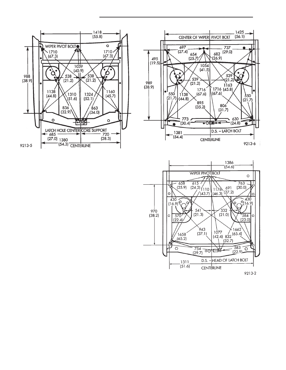
Fig. 5 Engine Compartment Dimensions—AP-Body
Fig. 3 Engine Compartment Dimensions—AG-Body
Fig. 4 Engine Compartment Dimensions—AJ-Body
13 - 10
FRAME AND BUMPERS
Ä
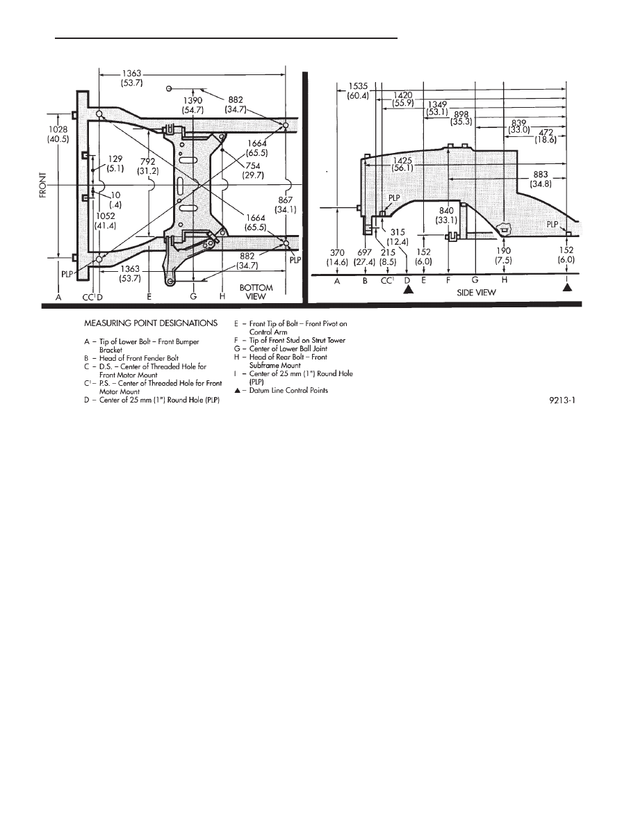
Fig. 6 Front Frame Dimensions—All
Ä
FRAME AND BUMPERS
13 - 11
Нет комментариевНе стесняйтесь поделиться с нами вашим ценным мнением.
Текст