Chrysler Le Baron, Dodge Dynasty, Plymouth Acclaim. Manual — part 51
The engine start-up (crank), engine warm-up, and
wide open throttle modes are OPEN LOOP modes. The
acceleration, deceleration, and cruise modes, with the
engine at operating temperature are CLOSED
LOOP modes (under most operating conditions).
IGNITION SWITCH ON (ZERO RPM) MODE
When the multi-port fuel injection system is acti-
vated by the ignition switch, the following actions
occur:
• The PCM determines atmospheric air pressure from
the MAP sensor input to determine basic fuel strategy.
• The PCM monitors the coolant temperature sensor
and throttle position sensor input. The PCM modifies
fuel strategy based on these inputs.
When the key is in the ON position and the engine is
not running (zero rpm), the auto shutdown (ASD) relay
and fuel pump relay are not energized. Therefore
battery voltage is not supplied to the fuel pump,
ignition coil, fuel injectors or oxygen sensor heating
element.
ENGINE START-UP MODE
This is an OPEN LOOP mode. The following actions
occur when the starter motor is engaged.
If the PCM receives a distributor signal, it energizes
the auto shutdown (ASD) relay and fuel pump relay.
These relays supply battery voltage to the fuel pump,
fuel injectors, ignition coil, and oxygen sensor heating
element. If the PCM does not receive a distributor
input, the ASD relay and fuel pump relay will be
de-energized after approximately one second.
The PCM energizes all six injectors until it deter-
mines crankshaft position from the distributor pick-up
signals. The PCM determines crankshaft position
within 2 engine revolutions.
After determining crankshaft position, the PCM be-
gins energizing the injectors in sequence. The PCM
adjusts injector pulse width and controls injector syn-
chronization by turning the individual ground paths to
the injectors On and Off.
When the engine idles within
664 RPM of its target
RPM, the PCM compares current MAP sensor value
with the atmospheric pressure value received during
the Ignition Switch On (zero RPM) mode. If the PCM
does not detect a minimum difference between the two
values, it sets a MAP fault into memory.
Once the ASD and fuel pump relays have been
energized, the PCM:
• determines injector pulse width based on coolant
temperature, manifold absolute pressure (MAP) and
the number of engine revolutions since cranking was
initiated.
• monitors the coolant temperature sensor, distribu-
tor pick-up, MAP sensor, and throttle position sensor
to determine correct ignition timing.
ENGINE WARM-UP MODE
This is a OPEN LOOP mode. The following inputs
are received by the PCM:
• engine coolant temperature
• crankshaft position (distributor pick-up)
• manifold absolute pressure (MAP)
• engine speed (distributor pick-up)
• throttle position
• A/C switch
• battery voltage
The PCM adjusts injector pulse width and controls
injector synchronization by turning the individual
ground paths to the injectors On and Off.
The PCM adjusts engine idle speed by regulating
the idle air control motor and ignition timing.
CRUISE OR IDLE MODE
When the engine is at operating temperature this
is a CLOSED LOOP mode. During cruising speed the
following inputs are received by the PCM:
• engine coolant temperature
• crankshaft position (distributor pick-up)
• manifold absolute pressure
• engine speed (distributor pick-up)
• throttle position
• exhaust gas oxygen content
• A/C control positions
• battery voltage
The PCM adjusts injector pulse width and controls
injector synchronization by turning the individual
ground paths to the injectors On and Off.
The PCM adjusts engine idle speed and ignition
timing. The PCM controls the air/fuel ratio according
to the oxygen content in the exhaust gas.
ACCELERATION MODE
This is a CLOSED LOOP mode. The PCM recog-
nizes an abrupt increase in throttle position or MAP
pressure as a demand for increased engine output
and vehicle acceleration. The PCM increases injector
pulse width in response to increased fuel demand.
DECELERATION MODE
This is a CLOSED LOOP mode. During decelera-
tion the following inputs are received by the PCM:
• engine coolant temperature
• crankshaft position (distributor pick-up)
• manifold absolute pressure
• engine speed (distributor pick-up)
• throttle position
• exhaust gas oxygen content
• A/C control positions
• battery voltage
14 - 122
FUEL SYSTEMS
Ä
The PCM may receive a closed throttle input from
the throttle position sensor (TPS) when it senses an
abrupt decrease in manifold pressure. This indicates
a hard deceleration. The PCM may reduce injector
firing to once per engine revolution. This helps main-
tain better control of the air-fuel mixture.
During a deceleration condition, the PCM grounds
the exhaust gas recirculation (EGR) solenoid. When
the PCM grounds the solenoid, preventing EGR.
WIDE OPEN THROTTLE MODE
This is an OPEN LOOP mode. During wide-open-
throttle operation, the following inputs are received
by the PCM:
• engine coolant temperature
• crankshaft position (distributor pick-up)
• manifold absolute pressure
• engine speed (distributor pick-up)
• throttle position
When the PCM senses wide open throttle condition
through the throttle position sensor (TPS) it will:
• Provide a ground for the electrical EGR transducer
(EET) solenoid. When the PCM grounds the solenoid,
the EGR system stops operating.
• De-energize the air conditioning relay. This dis-
ables the air conditioning system.
The exhaust gas oxygen content input is not ac-
cepted by the PCM during wide open throttle opera-
tion. The PCM will adjust injector pulse width to
supply a predetermined amount of additional fuel.
IGNITION SWITCH OFF MODE
When the ignition switch is turned to the OFF po-
sition, the following occurs:
• All outputs are turned off.
• No inputs are monitored.
• The PCM shuts down.
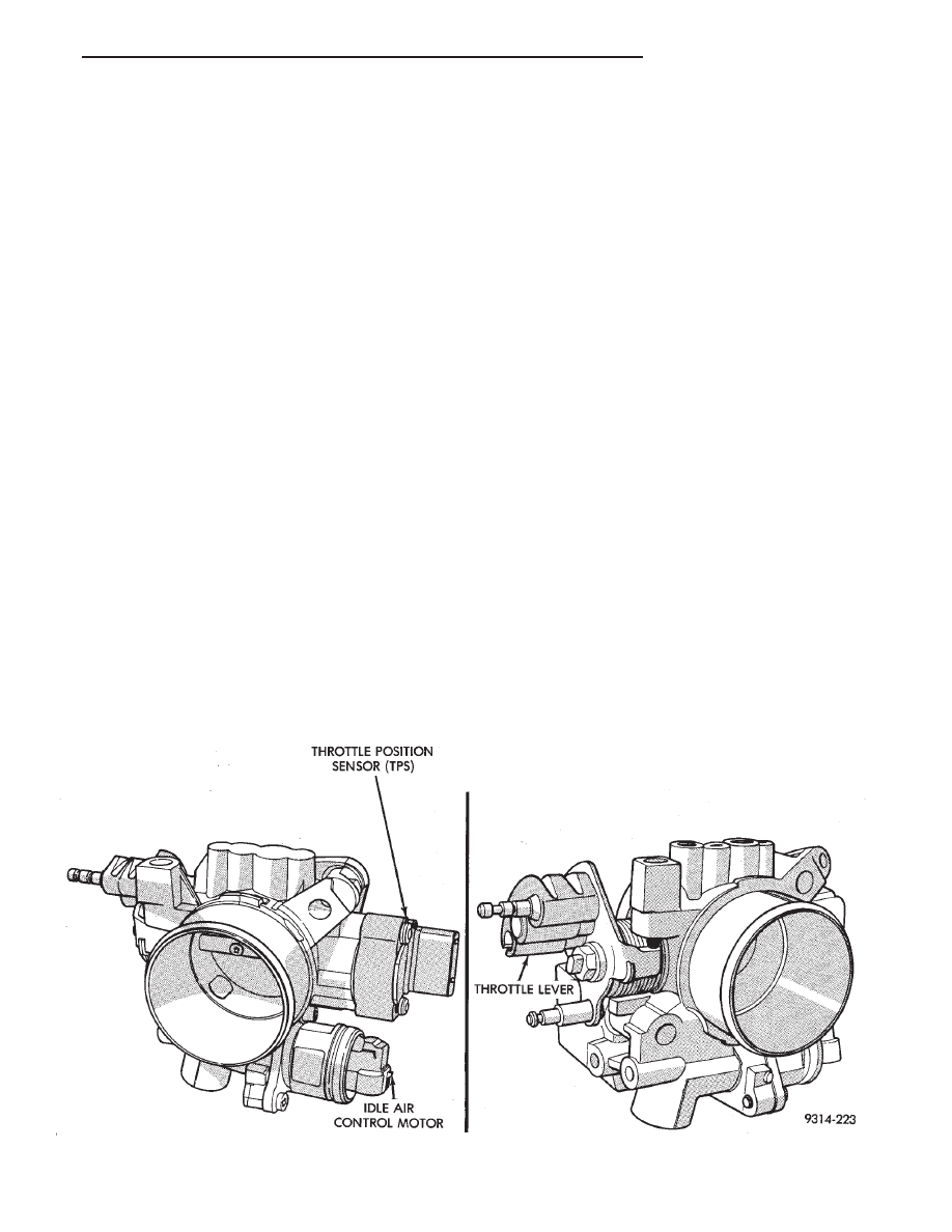
THROTTLE BODY
The throttle body assembly (Fig. 19) is located at
the left end of the air intake plenum. The throttle
body houses the throttle position sensor and the idle
air control motor. Air flow through the throttle body
is controlled by a cable operated throttle blade lo-
cated in the base of the throttle body.
FUEL SUPPLY CIRCUIT
Fuel is supplied to the fuel rail by an electric pump
mounted in the fuel tank. The pump inlet is fitted
with a strainer to prevent water and other contami-
nants from entering the fuel supply circuit.
Fuel pressure is controlled to a preset level above
intake manifold pressure by a pressure regulator.
The pressure regulator is mounted on the fuel rail.
The regulator uses intake manifold pressure as a ref-
erence.
Fig. 19 Throttle Body
Ä
FUEL SYSTEMS
14 - 123
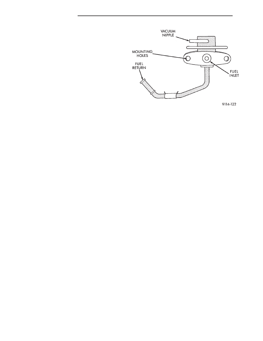
FUEL PRESSURE REGULATOR
The pressure regulator is a mechanical device lo-
cated on the fuel rail, downstream of the fuel injec-
tors (Fig. 20). The regulator maintains a constant
328 kPa (47.6 psi) across the fuel injector tip.
The regulator contains a spring loaded rubber dia-
phragm that covers the fuel return port. When the
fuel pump is operating, fuel flows past the injectors
into the regulator. Fuel is restricted from flowing
any further by the blocked return port. When fuel
pressure reaches 328 kPa (47.6 psi) it pushes on the
diaphragm, compresses the spring, and uncovers the
fuel return port. The diaphragm and spring con-
stantly move from an open to closed position to keep
the fuel pressure constant.
Fig. 20 Fuel Pressure Regulator
14 - 124
FUEL SYSTEMS
Ä

3.0L MULTI-PORT FUEL INJECTION—GENERAL DIAGNOSIS
INDEX
page
page
Fuel System Diagram
. . . . . . . . . . . . . . . . . . . . 125
Visual Inspection
. . . . . . . . . . . . . . . . . . . . . . . . 125
FUEL SYSTEM DIAGRAM
The 3.0L MPI system is managed by the PCM. The
PCM receives inputs from various switches and sen-
sors (Fig. 1). Based on these inputs, the PCM adjusts
ignition timing and idle speed through various out-
put devices. Refer to the Multi-Port Fuel Injec-
tion—3.0L Engine section of this group for system
and component descriptions.
VISUAL INSPECTION
Perform a visual inspection for loose, disconnected,
or misrouted wires and hoses before diagnosing or
servicing the fuel injection system. A visual check
saves unnecessary test and diagnostic time. A thor-
ough visual inspection includes the following checks:
(1) Check for correct spark plug cable routing. En-
sure the cables are completely connected to the spark
plugs and distributor.
(2) Check ignition coil electrical connections (Fig.
2).
(3) Verify the electrical connector is attached to
the Purge Solenoid (Fig. 3).
Fig. 1 Multi-Port Fuel Injection Components
Fig. 2 Ignition Coil Electrical Connection
Ä
FUEL SYSTEMS
14 - 125
Нет комментариевНе стесняйтесь поделиться с нами вашим ценным мнением.
Текст