Chrysler Le Baron, Dodge Dynasty, Plymouth Acclaim. Manual — part 49
• Engine Coolant Temperature Sensor
• Distributor Pick-up
• Manifold Absolute Pressure (MAP) Sensor
• Oxygen Sensor
• SCI Receive
• Speed Control System Controls
• Throttle Position Sensor
• Park/Neutral Switch (automatic transaxle)
• Vehicle Speed Sensor
PCM Outputs:
• Air Conditioning Clutch Relay
• Generator Field
• Idle Air Control Motor
• Auto Shutdown (ASD) and Fuel Pump Relays
• Canister Purge Solenoid
• Malfunction Indicator Lamp (Check Engine Lamp)
• Data Link Connector
• Electric EGR Transducer (EET)
• Fuel Injectors
• Ignition Coil
• Torque Converter Clutch Solenoid
• Radiator Fan Relay
• Speed Control Solenoids
• Tachometer Output
Based on inputs it receives, the PCM adjusts fuel
injector pulse width, idle speed, ignition spark ad-
vance, ignition coil dwell and canister purge opera-
tion.
The
PCM
regulates
the
cooling
fan,
air
conditioning and speed control systems. The PCM
changes generator charge rate by adjusting the gen-
erator field.
The PCM adjusts injector pulse width (air-fuel ra-
tio) based on the following inputs.
• battery voltage
• engine coolant temperature
• exhaust gas content
• engine speed (distributor pick-up)
• manifold absolute pressure
• throttle position
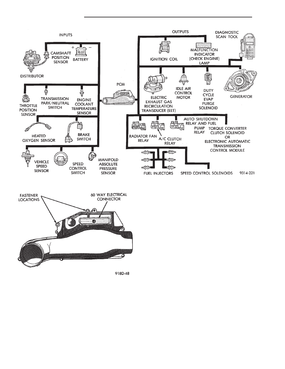
Fig. 1 Multi-Port Fuel Injection Components
Fig. 2 PCM
14 - 114
FUEL SYSTEMS
Ä
The PCM adjusts ignition timing based on the fol-
lowing inputs.
• engine coolant temperature
• engine speed (distributor pick-up)
• manifold absolute pressure
• throttle position
The Automatic Shut Down (ASD) and Fuel Pump
relays are mounted externally, but turned on and off
by the PCM through the same circuit.
The distributor pick-up signal is sent to the PCM.
If the PCM does not receive a distributor signal
within approximately one second of engine cranking,
the ASD relay and fuel pump relay are deactivated.
When these relays are deactivated, power is shut off
to the fuel injector, ignition coil, oxygen sensor heat-
ing element and fuel pump.
The
PCM
contains
a
voltage
converter
that
changes battery voltage to a regulated 8.0 volts. The
8.0 volts power the distributor pick-up and vehicle
speed sensor. The PCM also provides a 5.0 volts sup-
ply for the coolant temperature sensor, manifold ab-
solute pressure sensor and throttle position sensor.
AIR CONDITIONING SWITCH SENSE (AA, AG, AJ
BODY)—PCM INPUT
When the air conditioning or defrost switch is in
the ON position and the low pressure and high pres-
sure switches are closed, the PCM receives an input
for air conditioning. After receiving this input, the
PCM activates the A/C compressor clutch by ground-
ing the A/C clutch relay. The PCM also adjusts idle
speed to a scheduled RPM to compensate for in-
creased engine load.
AIR CONDITIONING SWITCH SENSE (AC
BODY)—PCM INPUT
When the air conditioning or defrost switch is in
the ON position and the low pressure, high pressure
and ambient temperature switches are closed, the
PCM receives an input for air conditioning. After re-
ceiving this input, the PCM activates the A/C com-
pressor clutch by grounding the A/C clutch relay.
The PCM also adjusts idle speed to a scheduled RPM
to compensate for increased engine load.
BATTERY VOLTAGE—PCM INPUT
The PCM monitors the battery voltage input to de-
termine fuel injector pulse width and generator field
control. If battery voltage is low, the PCM will in-
crease injector pulse width.
BRAKE SWITCH—PCM INPUT
When the brake switch is activated, the PCM re-
ceives an input indicating that the brakes are being
applied. After receiving this input the PCM main-
tains idle speed to a scheduled RPM through the idle
air control motor. The brake switch is mounted on
the brake pedal support bracket.
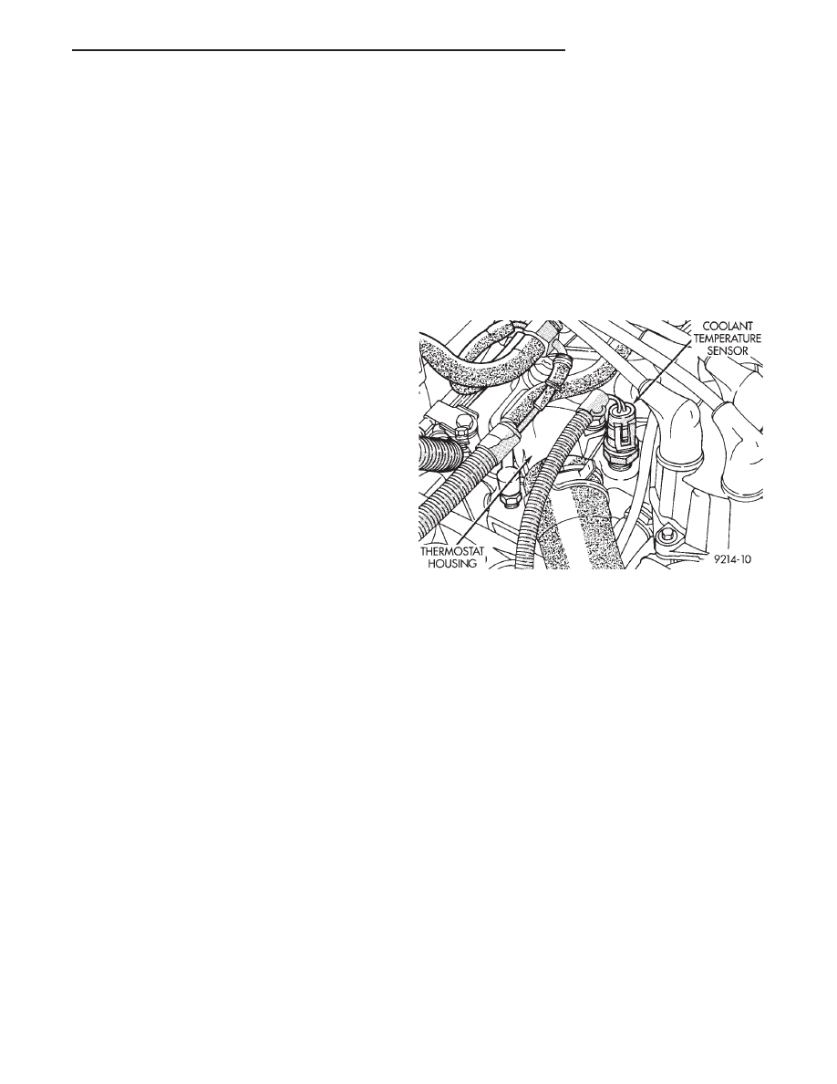
ENGINE COOLANT TEMPERATURE SENSOR—PCM
INPUT
The coolant temperature sensor is a variable resis-
tor with a range of -40° to 265°. The sensor is in-
stalled next to the thermostat housing.
The PCM supplies 5.0 volts to the coolant temper-
ature sensor. The sensor provides an input voltage to
the PCM (Fig. 3). As coolant temperature varies, the
sensors resistance changes, resulting in a different
input voltage to the PCM.
The PCM demands slightly richer air-fuel mixtures
and higher idle speeds until the engine reaches nor-
mal operating temperature.
This sensor is also used for cooling fan control.
DISTRIBUTOR PICK-UP—PCM INPUT
The distributor pick-up provides two inputs to the
PCM. From one input the PCM determines RPM (en-
gine speed). From the other input it derives crank-
shaft
position.
The
PCM
regulates
injector
synchronization and adjusts ignition timing and en-
gine speed based on these inputs.
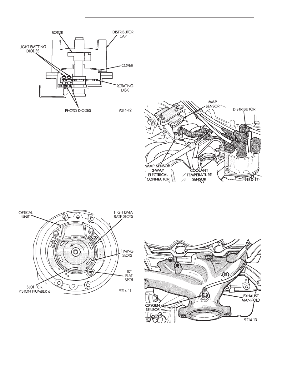
The distributor pick-up contains two signal gener-
ators. The pick-up unit consists of 2 light emitting
diodes (LED), 2 photo diodes, and a separate timing
disk. The timing disk contains two sets of slots. Each
set of slots rotates between a light emitting diode
and a photo diode (Fig. 4). The inner set contains 6
large slots, one for each cylinder. The outer set con-
tains several smaller slots.
The outer set of slots on the rotating disk repre-
sents 2 degrees of crankshaft rotation. Up to 1200
engine RPM, the PCM uses the input from the outer
set of slots to increase ignition timing accuracy.
The outer set of slots contains a 10 degree flat spot
(Fig. 5). The flat spot tells the PCM that the next
piston at TDC will be number 6. The position of each
piston is referenced by one of the six inner slots (Fig.
5).
As each slot on the timing disk passes between the
diodes, the beam from the light emitting diode is in-
Fig. 3 Coolant Temperature Sensor
Ä
FUEL SYSTEMS
14 - 115
terrupted. This creates an alternating voltage in
each photo diode which is converted into on-off
pulses. The pulses are the input to the PCM.
During
cranking,
the
PCM
cannot
determine
crankshaft position until the 10 degree flat spot on
the outer set of slots passes through the optical unit.
Once the flat spot is detected, the PCM knows piston
number 6 will be the next piston at TDC.
Since the disk rotates at half crankshaft speed, it
may take 2 engine revolutions during cranking for
the PCM to determine the position of piston number
6. For this reason the PCM will energize all six in-
jectors at the same time until it senses the position
of piston number 6.
MANIFOLD ABSOLUTE PRESSURE (MAP)
SENSOR—PCM INPUT
The PCM supplies 5 volts to the MAP sensor. The
Map sensor converts intake manifold pressure into
voltage. The PCM monitors the MAP sensor output
voltage. As vacuum increases, MAP sensor voltage
decreases proportionately. Also, as vacuum decreases,
MAP sensor voltage increases proportionately.
During cranking, before the engine starts running,
the PCM determines atmospheric air pressure from
the MAP sensor voltage. While the engine operates,
the PCM determines intake manifold pressure from
the MAP sensor voltage.
Based on MAP sensor voltage and inputs from
other sensors, the PCM adjusts spark advance and
the air/fuel mixture.
The MAP sensor (Fig. 6) mounts on a bracket at-
tached to the generator bracket. The sensor is con-
nected to the throttle body with a vacuum hose and
to the PCM electrically.
HEATED OXYGEN SENSOR (O
2
SENSOR)—PCM
INPUT
The O
2
sensor is located in the exhaust manifold
and provides an input voltage to the PCM. The input
tells the PCM the oxygen content of the exhaust gas
(Fig. 7). The PCM uses this information to fine tune
the air-fuel ratio by adjusting injector pulse width.
The O
2
sensor produces voltages from 0 to 1 volt,
depending upon the oxygen content of the exhaust
gas. When a large amount of oxygen is present
Fig. 4 Distributor Pick-up
Fig. 5 Inner and Outer Slots of Rotating Disk
Fig. 6 Map Sensor
Fig. 7 Heated Oxygen Sensor—3.0L Engine
14 - 116
FUEL SYSTEMS
Ä
(caused by a lean air-fuel mixture), the sensor pro-
duces a low voltage. When there is a lesser amount
present (rich air-fuel mixture) it produces a higher
voltage. By monitoring the oxygen content and con-
verting it to electrical voltage, the sensor acts as a
rich-lean switch.
The oxygen sensor is equipped with a heating ele-
ment that keeps the sensor at proper operating tem-
perature during all operating modes. Maintaining
correct sensor temperature at all times allows the
system to enter into Closed Loop operation sooner.
Also, it allow the system to remain in Closed Loop
operation during periods of extended idle.
In Closed Loop operation the PCM monitors the O
2
sensor input (along with other inputs) and adjusts
the injector pulse width accordingly. During Open
Loop operation the PCM ignores the O
2
sensor input.
The PCM adjusts injector pulse width based on pre-
programmed (fixed) values and from inputs of other
sensors.
SPEED CONTROL—PCM INPUT
The speed control system provides four separate
voltages (inputs) to the PCM. The voltages corre-
spond to the On/Off, Set, and Resume.
The speed control ON voltage informs the PCM
that the speed control system has been activated.
The speed control SET voltage informs the PCM that
a fixed vehicle speed has been selected. The speed
control RESUME voltage indicates the previous fixed
speed is requested. The speed control OFF voltage
tells the PCM that the speed control system has de-
activated. Refer to Group 8H for further speed con-
trol information.
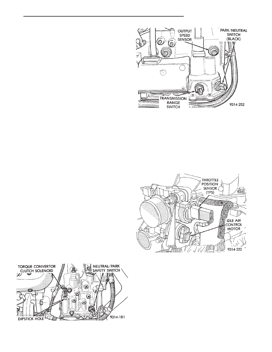
PARK/NEUTRAL SWITCH—PCM INPUT
The park/neutral switch is located on the transaxle
housing (Fig. 8 or Fig. 9). It provides an input to the
PCM indicating whether the automatic transaxle is
in Park or Neutral. This input is used to determine
idle speed (varying with gear selection), fuel injector
pulse width, and ignition timing advance. The park/
neutral switch is sometimes referred to as the neu-
tral safety switch.
THROTTLE POSITION SENSOR (TPS)—PCM INPUT
The Throttle Position Sensor (TPS) is mounted on
the throttle body and connected to the throttle blade
shaft (Fig. 10). The TPS is a variable resistor that
provides the PCM with an input signal (voltage) rep-
resenting throttle blade position. As the position of
the throttle blade changes, the resistance of the TPS
changes.
The PCM supplies approximately 5 volts to the
TPS. The TPS output voltage (input signal to the
PCM) represents throttle blade position. The TPS
output voltage to the PCM varies from approxi-
mately 0.5 volt at minimum throttle opening (idle) to
3.5 volts at wide open throttle. The wide open throt-
tle input is approximately 3 volts more than the min-
imum throttle opening value.
Along with inputs from other sensors, the PCM
uses the TPS input to determine current engine op-
erating conditions. After determining the current op-
erating conditions, the PCM adjust fuel injector pulse
width and ignition timing.
Fig. 8 Park Neutral Switch—3-Speed Automatic
Transaxle
Fig. 9 Park Neutral Switch—4-Speed Electronic
Automatic Transaxle
Fig. 10 Throttle Position Sensor
Ä
FUEL SYSTEMS
14 - 117
Нет комментариевНе стесняйтесь поделиться с нами вашим ценным мнением.
Текст