Chrysler Le Baron, Dodge Dynasty, Plymouth Acclaim. Manual — part 310
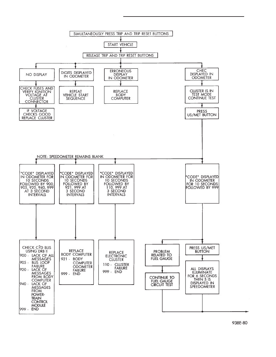
Fig. 24 Electronic Cluster Self-Diagnostic Test
8E - 52
INSTRUMENT PANEL AND GAUGES
Ä
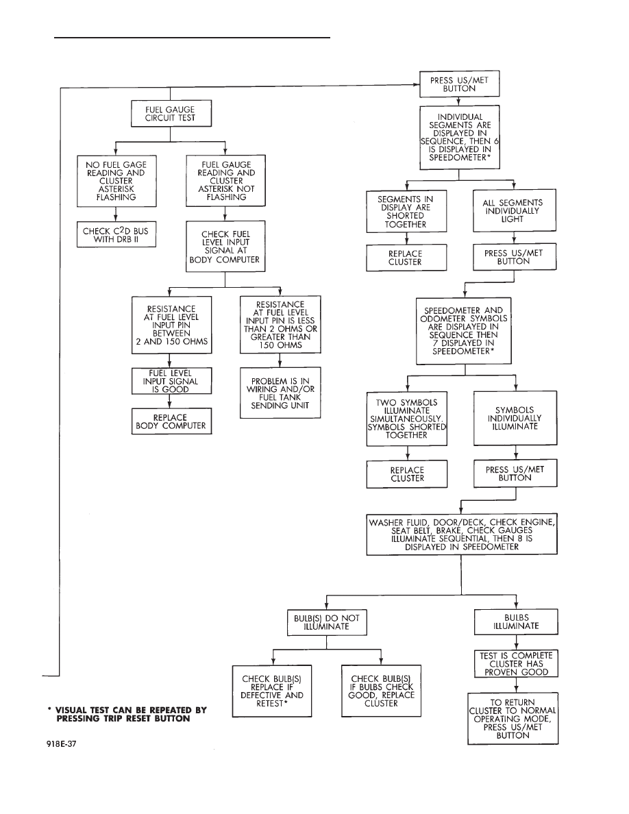
Fig. 25 Electronic Cluster Self-Diagnostic Test—Continued
Ä
INSTRUMENT PANEL AND GAUGES
8E - 53

INSTALLATION
(1) Latch switch linkage in the up position.
(2) Insert dimmer shaft into dimmer knob while
aligning switch in to switch pod assembly.
(3) Install switch attaching screws.
(4) Unlatch linkage and install onto push buttons.
(5) Operate all switch modes for correct operation.
(6) Install turn signal switch.
(7) Reconnect wiring for turn signal switch, mak-
ing sure wire is properly clipped into position.
(8) Place together the inner and outer bezels. In-
stall five inner switch pod panel screws and three
screws from underneath the switch pod.
(9) Install turn signal lever by pushing straight
into switch assembly.
(10) Install switch pod assembly.
LOWER STEERING COLUMN COVER
REMOVAL
(1) Remove screws along top edge of cover.
(2) Remove screw at each lower corner of cover.
(3) Remove cover from underneath over column
cover.
(4) For installation reverse above procedures.
GLOVEBOX MODULE REMOVAL
(1) Disconnect battery negative cable and isolate
or remove fuse #26 prior to removing switch or wires
may short to ground.
(2) Remove cowl side trim panel.
(3) Remove screws at right end of glovebox and
lower corners.
(4) Open glovebox, remove light and disconnect
wiring.
(5) Remove five screws along top of glovebox frame
and screw at each lower corner.
(6) Remove glovebox assembly.
(7) For installation reverse above procedures.
CONCEALED HEADLAMP MODULE REMOVAL
(1) Remove left under panel silencer.
(2) Slide module off bayonet bracket while disen-
gaging spring retainer.
(3) Disconnect wiring terminal.
(4) For installation reverse above procedures.
HOOD RELEASE REMOVE
(1) Remove lower column cover.
(2) Remove screws on fuse block and move aside.
(3) Remove screws on hood release assembly to re-
move.
(4) For installation reverse above procedures.
AIR CONDITIONING CONTROL REMOVE
(1) Remove center stack bezel.
(2) Remove two control mounting screws (Fig. 28
and 29).
(3) Slide control rearward, disconnect cable, vac-
uum harness, and electrical wiring. With automatic
temperature control, disconnect wiring connector; be-
ing careful not to break off locking tab.
(4) For installation reverse above procedures.
Fig. 26 Switch Pod Assembly
Fig. 27 Headlamp Multi-Function Switch
Fig. 28 A/C Control
8E - 54
INSTRUMENT PANEL AND GAUGES
Ä
AUTOMATIC TEMPERATURE CONTROL LAMP
REMOVAL
(1) Remove automatic temperature control from in-
strument panel.
(2) Remove top cover screw and unsnap cover from
control (Fig. 30).
(3) Remove four screws that connect computer
housing to the button housing.
(4) Unsnap the button housing from the computer
housing.
(5) Remove lamps by turning in a counter clock-
wise direction and install lamps by turning in a
clockwise direction.
(6) For
installation
reverse
above
procedures.
When finish perform ATC system function test.
GLOVE BOX LAMP AND SWITCH REMOVAL
(1) Disconnect battery negative cable and isolate
or remove fuse #26 prior to removing switch or wires
may short to ground.
(2) Open glove box door.
(3) Remove lamp and test. If bad replace lamp. If
OK proceed to step 3.
(4) Carefully pry switch from its mounting surface
with tip of a small pry bar.
(5) Remove switch from glove box and disconnect
electrical leads and test for battery voltage and
ground.
(6) If OK test switch for continuity. If bad replace
switch.
(7) For installation reverse above procedures.
ENGINE COMPARTMENT NODE
The Engine Compartment Node is a microcomputer
controlled unit which informs the EVIC overhead
console via the CCD bus of outside temperature, com-
pass direction and the following warning messages:
• Brake Fluid
• Low Coolant Level
• Low Engine Oil Level
The Engine Compartment Node is located behind
the front bumper reinforcement.
For complete diagnostic procedures for the Engine
Compartment Node, refer to the AG and AJ Body Di-
agnostic Procedures Manual.
TRAVELER/EVIC REMOVAL
To test Traveler/EVIC, refer to AG, AJ Body Diag-
nostic Procedure.
(1) Remove cluster stack bezel.
(2) Remove three screws and disconnect wiring
connector.
(3) For installation reverse above procedures.
BEZEL WITH/WITHOUT MESSAGE CENTER
REMOVAL
(1) Use a straight edge tool to pry out one end of
the message center and continue to disengage six
clips along the length of the message center.
(2) Remove the message center and disconnect the
wiring.
(3) For installation reverse the above procedures.
CONSOLE SWITCH PLATE/CUBBY BOX
REMOVAL
(1) Pry up edge of switch plate or cubby box.
(2) Disconnect wiring terminal to switch plate if so
equipped.
(3) For installation reverse above procedures.
CIGAR LIGHTER REMOVAL
(1) Remove center bezel.
(2) Remove two center console attaching screws.
(3) Remove ash receptacle/cup holder.
(4) Remove two screws underneath ash receptacle/
cup holder.
(5) Remove ash receiver/bezel.
(6) Disconnect wiring connectors from lighter re-
ceptacle.
Fig. 29 Automatic Temperature Control
Fig. 30 Automatic Temperature Control Lamp
Ä
INSTRUMENT PANEL AND GAUGES
8E - 55
Нет комментариевНе стесняйтесь поделиться с нами вашим ценным мнением.
Текст