Chrysler Le Baron, Dodge Dynasty, Plymouth Acclaim. Manual — part 309

helper depresses brake pedal and observes warning
lamp. If lamp fails to light, inspect for a burned out
lamp, disconnected socket, a broken or disconnected
wire at switch.
If lamp is not burned out and wire continuity is
proven, replace brake warning switch in brake line
TEE fitting mounted on frame rail in engine com-
partment below master cylinder (Fig.16).
CAUTION: If wheel cylinder bleeder was opened
check master cylinder fluid level.
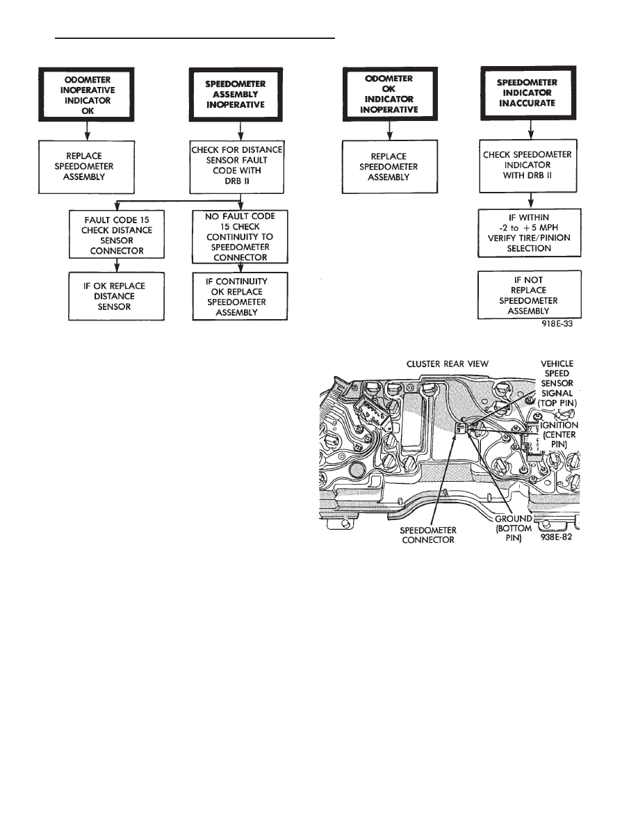
SPEEDOMETER SYSTEM
The
vehicles
are
equipped
with
electronically
driven speedometer and odometer assemblies. The
unit has the same appearance as a conventional
speedometer but it eliminates the cable-driven me-
chanical system. A signal is sent from a transmis-
sion-mounted
vehicle
speed
sensor
to
the
speedometer circuitry through the wiring harness.
By eliminating the speedometer cable, instrument
cluster service and removal is improved. Refer to Fig.
17 Speedometer Diagnosis Chart.
When the speedometer is out of calibration. The
electronic automatic transaxle vehicle speed sensor
output must be calibrated to reflect the different
combinations of equipment. The procedure is called
Pinion Factor, refer to Group 21, Transaxle for the
procedure.
Fig. 15 Brake System Warning Lamp Diagnosis
Fig. 16 Brake Warning Lamp Switch
8E - 48
INSTRUMENT PANEL AND GAUGES
Ä
SPEEDOMETER/ODOMETER ASSEMBLY
REMOVAL
(1) Remove switch pod assembly.
(2) Remove cluster, refer to Cluster Removal.
(3) Remove mask and lens assembly.
(4) Remove tachometer, turbo gauge.
(5) Remove volt, temperature, oil and fuel gauge
assemblies.
(6) Remove the speedometer/odometer assembly
from the cluster housing.
(7) Disconnect pigtail connector from the cluster
printed circuit board.
(8) For installation reverse above procedures. Lis-
ten for the pigtail connector to snap in place.
SPEEDOMETER CIRCUIT TESTING
(1) Using DRB II, check vehicle speed sensor for
speed sensor fault code and for proper speed indica-
tion. Refer to Powertrain Diagnostics Procedure
Manual; Speed Control Test (Fig. 18).
(2) Remove cluster, but do not disconnect cluster
wiring.
(3) With ignition ON check for battery voltage
across the ignition pin and ground pin of speedome-
ter connector.
(4) Check for continuity from vehicle speed sensor
signal pin to connector at speed sensor.
(5) Check cluster to body for continuity to ground.
(6) If all these tests prove good, replace speedome-
ter.
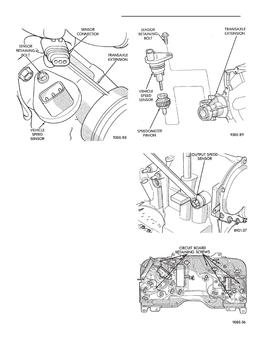
VEHICLE SPEED SENSOR REPLACEMENT
(1) Remove harness connector from sensor and
make sure weather seal is on harness connector.
(2) Remove sensor retaining bolt (Fig. 19).
(3) Pull sensor and pinion gear assembly out of
transaxle. If necessary carefully pry loose with a flat
blade screwdriver (Fig. 20).
(4) Remove pinion gear from sensor.
(5) For installation reverse above procedures. Seat
the sensor assembly by hand to ensure proper gear
engagement. Tighten retaining bolt to 7 N
Im (60 in.
lbs.) torque.
ELECTRONIC AUTOMATIC TRANSAXLE
VEHICLE SPEED SENSOR REPLACEMENT
The output vehicle speed sensor is located to the
left of the manual shift lever.
(1) Raise and support vehicle on safety stands.
(2) Remove vehicle speed sensor (Fig. 21).
(3) For installation, reverse above procedures.
Fig. 17 Speedometer Diagnosis
Fig. 18 Speedometer
Ä
INSTRUMENT PANEL AND GAUGES
8E - 49
VEHICLE SPEED SENSOR TEST
For testing of the vehicle speed sensor and related
components using DRB II, refer to the appropriate
Powertrain Diagnostics Test Procedure Manual.
TACHOMETER DRIVE MODULE REMOVAL
(1) Remove cluster assembly.
(2) Pull tachometer drive module from printed cir-
cuit board (Fig. 22).
(3) For installation reverse above procedures. Use
care when aligning module to printed circuit board.
PRINTED CIRCUIT BOARD REMOVAL
(1) Remove cluster assembly.
(2) Remove mounting screws securing printed cir-
cuit board to cluster housing.
(3) Remove tachometer drive module (Fig. 22).
(4) Twist out all lamp sockets.
(5) For installation reverse above procedures.
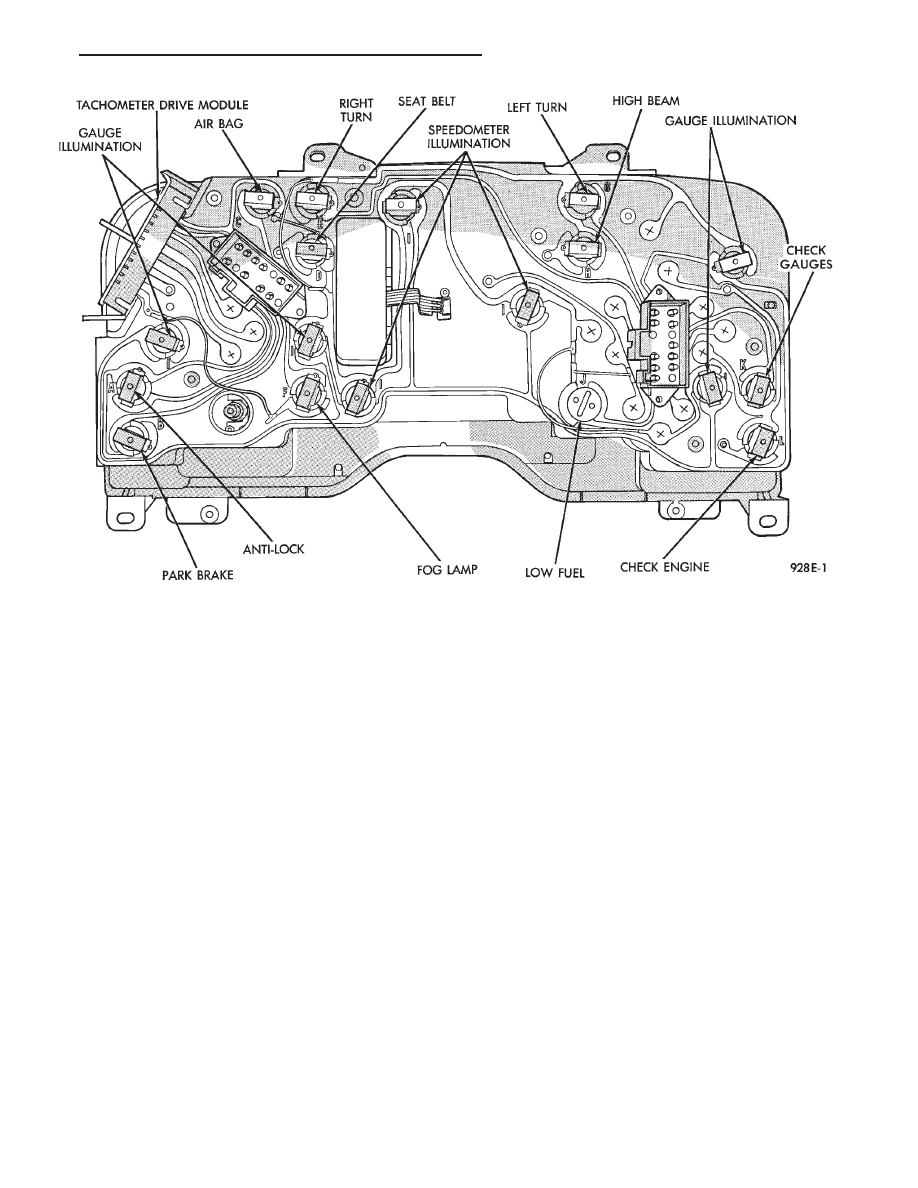
CLUSTER LAMPS REMOVAL—MECHANIAL
CLUSTER ONLY
(1) Remove cluster assembly (Fig. 23).
(2) Remove one piece integral lamp and socket
from rear of cluster.
ELECTRONIC CLUSTER
Refer to Body Diagnostic Procedures Manual when
using DRB II.
SELF DIAGNOSTIC SYSTEM
The electronic clusters have an internal diagnostic
routing to isolate problems within the cluster.
Fig. 20 Vehicle Speed Sensor and Speedometer Pinion
Fig. 21 Vehicle Speed Sensor Removal
Fig. 22 Cluster Printed Circuit Board
Fig. 19 Vehicle Speed Sensor and Connector
8E - 50
INSTRUMENT PANEL AND GAUGES
Ä
Perform cluster Self Diagnostic Test to determine
whether problem is within cluster or outside of clus-
ter.
Refer to Fig. 24 and 25.
Successful completion of the SELF DIAGNOSTIC
TEST indicates that the problem is in the wiring,
connectors or sensors out side of the cluster.
CLUSTER ASSEMBLY REMOVAL
The electronic cluster which is serviced as an as-
sembly is removed with the same procedure as the
conventional cluster.
CONDITION: CLUSTER DISPLAYS DO NOT
ILLUMINATE AFTER VEHICLE IS STARTED
(1) Check fuses and verify battery and ignition
voltage at cluster connector.
(2) Check ground from cluster connector to instru-
ment panel ground stud.
SWITCH AND PANEL COMPONENT SERVICE
HEADLAMP SWITCH
The headlamp switch is located on the left side of
the switch pod. The switch controls the headlamps,
parking lamps, fog lamps and instrument light dim-
ming. If any of the switches require replacement the
entire headlamp switch assembly must be replaced
(Fig. 26 and 27).
REMOVAL
(1) Remove switch pod assembly from the instru-
ment panel. DO NOT attempt to remove instrument
cluster dimmer switch or wiper delay switch knob,
they are not removable.
(2) Remove turn signal switch lever by pulling
straight out of switch pod.
(3) Remove screws from bottom of switch pod.
(4) Separate inner and outer switch pod halves and
remove turn signal switch to gain access to screw.
(5) Remove five inner switch pod panel screws and
3 screws from underneath the switch pod. Separate
the inner bezel from the outer bezel.
(6) Remove switch mounting screws before discon-
necting linkage.
(7) Disconnect switch linkage from buttons. Pull
the linkage straight up from the switch/button to dis-
engage it and remove switch.
Fig. 23 Mechanical Cluster Lamp Location
Ä
INSTRUMENT PANEL AND GAUGES
8E - 51
Нет комментариевНе стесняйтесь поделиться с нами вашим ценным мнением.
Текст