Chrysler Le Baron, Dodge Dynasty, Plymouth Acclaim. Manual — part 29
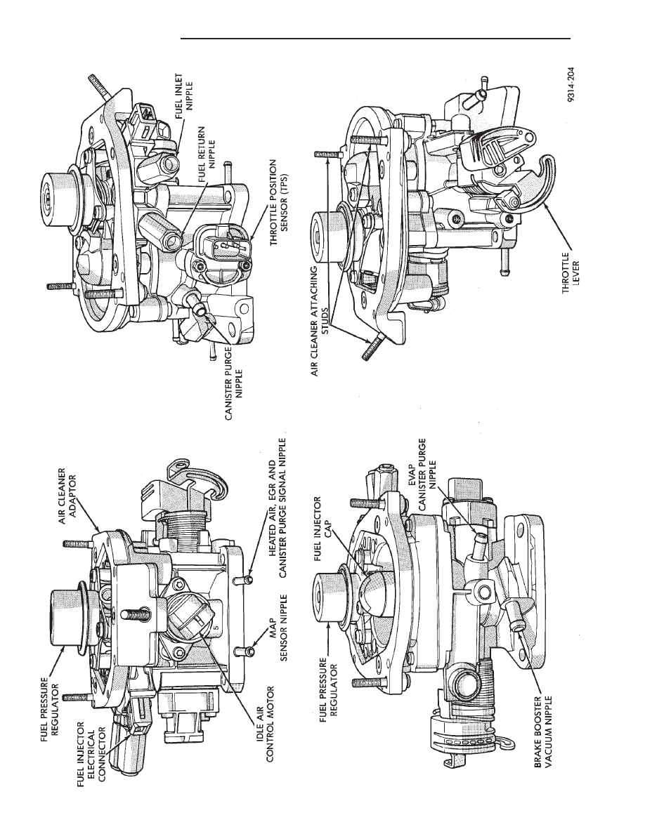
Fig.
18
Throttle
Body
14 - 34
FUEL SYSTEMS
Ä
2.2L/2.5L SINGLE POINT FUEL INJECTION—GENERAL DIAGNOSIS
INDEX
page
page
Fuel System Diagram
. . . . . . . . . . . . . . . . . . . . . 35
Visual Inspection
. . . . . . . . . . . . . . . . . . . . . . . . . 35
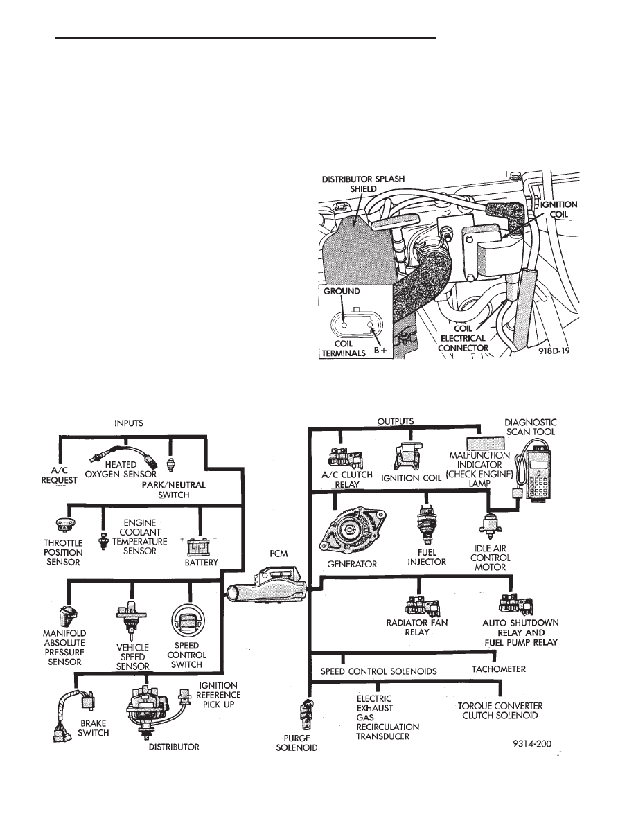
FUEL SYSTEM DIAGRAM
The fuel injection system is managed by the pow-
ertrain control module (PCM). The PCM receives in-
puts from various switches and sensors (Fig. 1).
Based on these inputs the PCM adjusts ignition tim-
ing and idle speed through output devices. Refer to
the Single Point Fuel Injection System Operation
section of this group for system and component de-
scriptions.
VISUAL INSPECTION
Perform a visual inspection for loose, disconnected,
or misrouted wires and hoses before diagnosing or
servicing the fuel injection system. A visual check
helps save unnecessary test and diagnostic time. A
thorough visual inspection includes the following
checks:
(1) Check Ignition Coil Electrical Connections (Fig.
2).
Fig. 1 Single Point Fuel Injection Components
Fig. 2 Ignition Coil
Ä
FUEL SYSTEMS
14 - 35
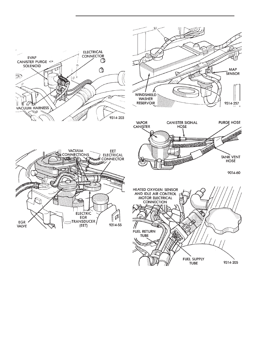
(2) Verify the electrical connector is attached to
the Canister Purge Solenoid (Fig. 3).
(3) Verify vacuum connection at Canister Purge
Solenoid is secure and not leaking.
(4) Verify the wiring connector is attached to the
Electric EGR Transducer (EET) solenoid (Fig. 4).
(5) Verify vacuum connection at the Electric EGR
Transducer is secure and not leaking (Fig. 4).
(6) Verify the connector is attached to the MAP
sensor (Fig. 5).
(7) Verify the vacuum hose is attached to the MAP
sensor (Fig. 5).
(8) Verify the generator wiring and belt are cor-
rectly installed and tightened.
(9) Verify hoses are securely attached to the EVAP
canister (Fig. 6).
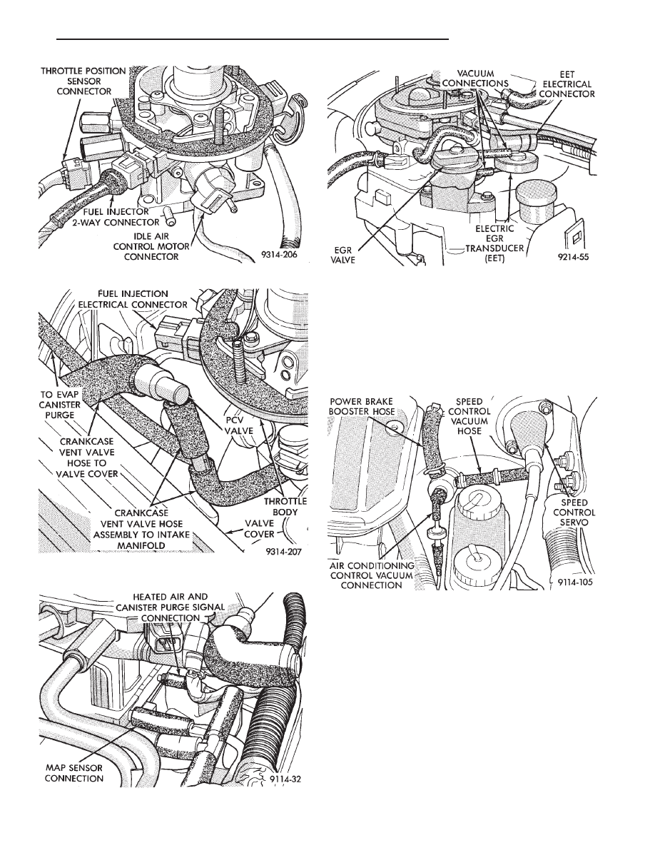
(10) Verify the throttle body wiring connection to
main harness is attached (Fig. 7).
(11) Verify the electrical connector is attached to
idle air control motor (Fig. 8).
(12) Verify the electrical connector is attached to
the throttle position sensor (Fig. 8).
(13) Verify the electrical connector is attached to
the fuel injector (Fig. 8).
(14) Verify the hose from PCV valve is securely at-
tached to the intake manifold vacuum port (Fig. 9).
(15) Verify vacuum connections on the front and
rear of Throttle Body are secure and not leaking
(Figs. 10 and 11).
Fig. 3 Canister Purge Solenoid
Fig. 4 Electric EGR Transducer (EET) Assembly
Fig. 5 Manifold Absolute Pressure (MAP) Sensor
Fig. 6 EVAP Canister
Fig. 7 Throttle Body Wiring Connection to Main
Harness
14 - 36
FUEL SYSTEMS
Ä
(16) Verify hoses are attached to back pressure
transducer or electric EGR transducer (EET) (Fig.
11).
(17) Verify heated air door vacuum connection is
connected and not leaking.
(18) Verify power brake and speed control vacuum
connectors are tight (Fig. 12).
(19) Verify all ignition cables are in correct order
and seated into place (Fig. 13).
(20) Verify the electrical connector is attached to
coolant temperature sensor (Fig. 14).
(21) Verify
battery
negative
ground
eyelet
is
mounted to the cylinder head (Figs. 14).
(22) Verify electrical connector is attached to dis-
tributor (Fig. 15).
(23) Verify radiator fan electrical connector is at-
tached to the harness (Fig. 15).
(24) Verify oil pressure switch electrical connector
is attached to the switch (Fig. 15).
Fig. 9 Vacuum Hose from Intake Manifold to PCV
Valve
Fig. 10 Throttle Body Vacuum Ports—Front
Fig. 8 Throttle Body Wiring Connections
Fig. 11 Throttle Body Vacuum Ports—Rear
Fig. 12 Power Brake and Speed Control Vacuum
Connection
Ä
FUEL SYSTEMS
14 - 37
Нет комментариевНе стесняйтесь поделиться с нами вашим ценным мнением.
Текст