Chrysler Le Baron, Dodge Dynasty, Plymouth Acclaim. Manual — part 30

(25) On automatic transaxle equipped vehicles,
verify the park/neutral position switch electrical con-
nector is attached to the switch (Fig. 16).
(26) On automatic transaxle equipped vehicles,
check the torque convertor lockup solenoid electrical
connection (Fig. 16).
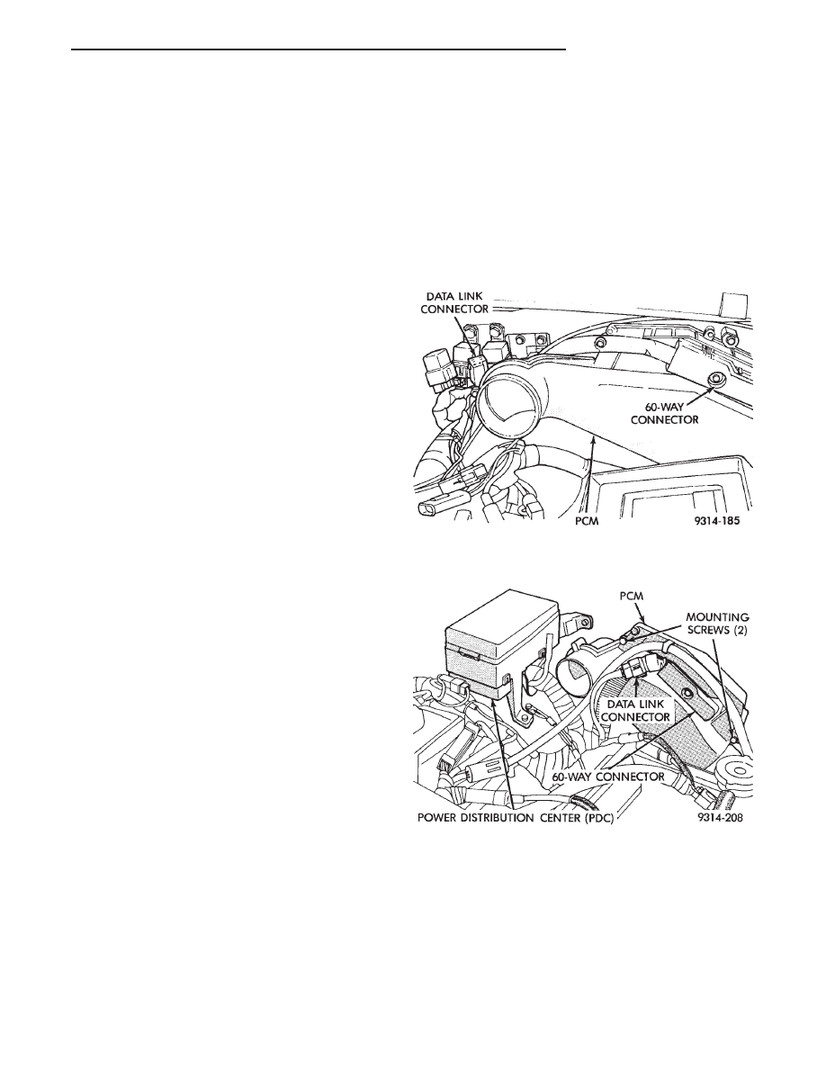
(27) Verify the 60-way connector is fully inserted
into the socket on the PCM (Fig. 17).
(28) Verify all electrical connectors are fully in-
serted into relays and that battery connections are
clean and tight (Figs. 18, 19, 20, 21, and 22).
Fig. 13 Ignition Cable Routing and Connection
Fig. 14 Coolant Temperature Sensor
Fig. 15 Distributor, Oil Pressure Switch, and
Radiator Fan Electrical Connections
Fig. 16 Automatic Transaxle Electrical Connections
Fig. 17 PCM Electrical Connector
14 - 38
FUEL SYSTEMS
Ä

(29) Verify engine harness to main harness con-
nections are fully inserted.
(30) Check the vehicle speed sensor connector (Fig.
23).
Fig. 18 Power Distribution Center (PDC) (AC Body)
Fig. 19 Relay Identification (AC Body)
Fig. 20 Relay Identification (AA and AP Bodies)
Fig. 21 Power Distribution Center (PDC) (AG and AJ
Body)
Fig. 22 Relay Identification (AG and AJ Body)
Fig. 23 Vehicle Speed Sensor Wiring Connection
Ä
FUEL SYSTEMS
14 - 39

(31) Verify engine ground strap is attached at the
engine and dash panel (Figs. 24 and 25).
(32) Verify oxygen sensor electrical connector is at-
tached to the sensor (Fig. 26).
(33) Check Hose and Wiring Connections at Fuel
Pump. Check that wiring connector is making con-
tact with terminals on pump.
Fig. 24 Engine Ground Strap at Intake Manifold
Fig. 25 Engine Ground Strap to Dash Panel
Fig. 26 Heated Oxygen Sensor Electrical
Connection
14 - 40
FUEL SYSTEMS
Ä
2.2L/2.5L SINGLE POINT FUEL INJECTION—ON-BOARD DIAGNOSTICS
INDEX
page
page
60-Way PCM Wiring Connector
. . . . . . . . . . . . . . 46
Circuit Actuation Test Mode
. . . . . . . . . . . . . . . . 45
Diagnostic Trouble Code Description
. . . . . . . . . . 42
General Information
. . . . . . . . . . . . . . . . . . . . . . . 41
High and Low Limits
. . . . . . . . . . . . . . . . . . . . . . 42
Ignition Timing Procedure
. . . . . . . . . . . . . . . . . . 46
Monitored Circuits
. . . . . . . . . . . . . . . . . . . . . . . . 41
Non-Monitored Circuits
. . . . . . . . . . . . . . . . . . . . 42
State Display Test Mode
. . . . . . . . . . . . . . . . . . . 45
Systems Test
. . . . . . . . . . . . . . . . . . . . . . . . . . . 45
Throttle Body Minimum Air Flow Check Procedure
GENERAL INFORMATION
The powertrain control module (PCM) has been
programmed to monitor many different circuits of the
fuel injection system. If a problem is sensed with a
monitored circuit often enough to indicate an actual
problem, the PCM stores a fault. If the problem is re-
paired or ceases to exist, the PCM cancels the Diag-
nostic Trouble Code after 50 to 100 vehicle key on/off
cycles.
Certain criteria must be met for a diagnostic trou-
ble code to be entered into powertrain control module
(PCM) memory. The criteria may be a specific range
of engine RPM, engine temperature, and/or input
voltage to the PCM.
It is possible that a diagnostic trouble code for a
monitored circuit may not be entered into memory
even though a malfunction has occurred. This may
happen because one of the diagnostic trouble code
criteria for the circuit has not been met. For exam-
ple, assume that one of the diagnostic trouble code
criteria for a certain sensor circuit is that the engine
must be operating between 750 and 2000 RPM to be
monitored for a diagnostic trouble code. If the sensor
output circuit shorts to ground when engine RPM is
above 2400 RPM (resulting in a 0 volt input to the
PCM) a diagnostic trouble code will not be entered
into memory. This is because the condition does not
occur within the specified RPM range.
There are several operating conditions for which
the PCM does not monitor and set diagnostic trouble
codes. Refer to Monitored Circuits and Non-Moni-
tored Circuits in this section.
Stored diagnostic trouble codes can be displayed by
cycling the ignition key On - Off - On - Off - On.
Also, the technician can display fault information us-
ing the DRB II scan tool. The DRBII scan tool con-
nects to the data link connector in the vehicle (Fig.
1, 2 or 3).
MONITORED CIRCUITS
The powertrain control module (PCM) can detect
certain fault conditions in the fuel injection system.
Open or Shorted Circuit - The PCM can deter-
mine if the sensor output (input to PCM) is within
proper range, and if the circuit is open or shorted.
Output Device Current Flow - The PCM senses
whether the output devices are hooked up. If there is
a problem with the circuit, the PCM senses whether
the circuit is open, shorted to ground, or shorted
high.
Oxygen Sensor - The PCM can determine if the
oxygen sensor is switching between rich and lean
Fig. 1 Data Link Connector Location—AA and AP
Vehicles
Fig. 2 Data Link Connector Location—AC Vehicles
Ä
FUEL SYSTEMS
14 - 41
Нет комментариевНе стесняйтесь поделиться с нами вашим ценным мнением.
Текст