Chrysler Le Baron, Dodge Dynasty, Plymouth Acclaim. Manual — part 202
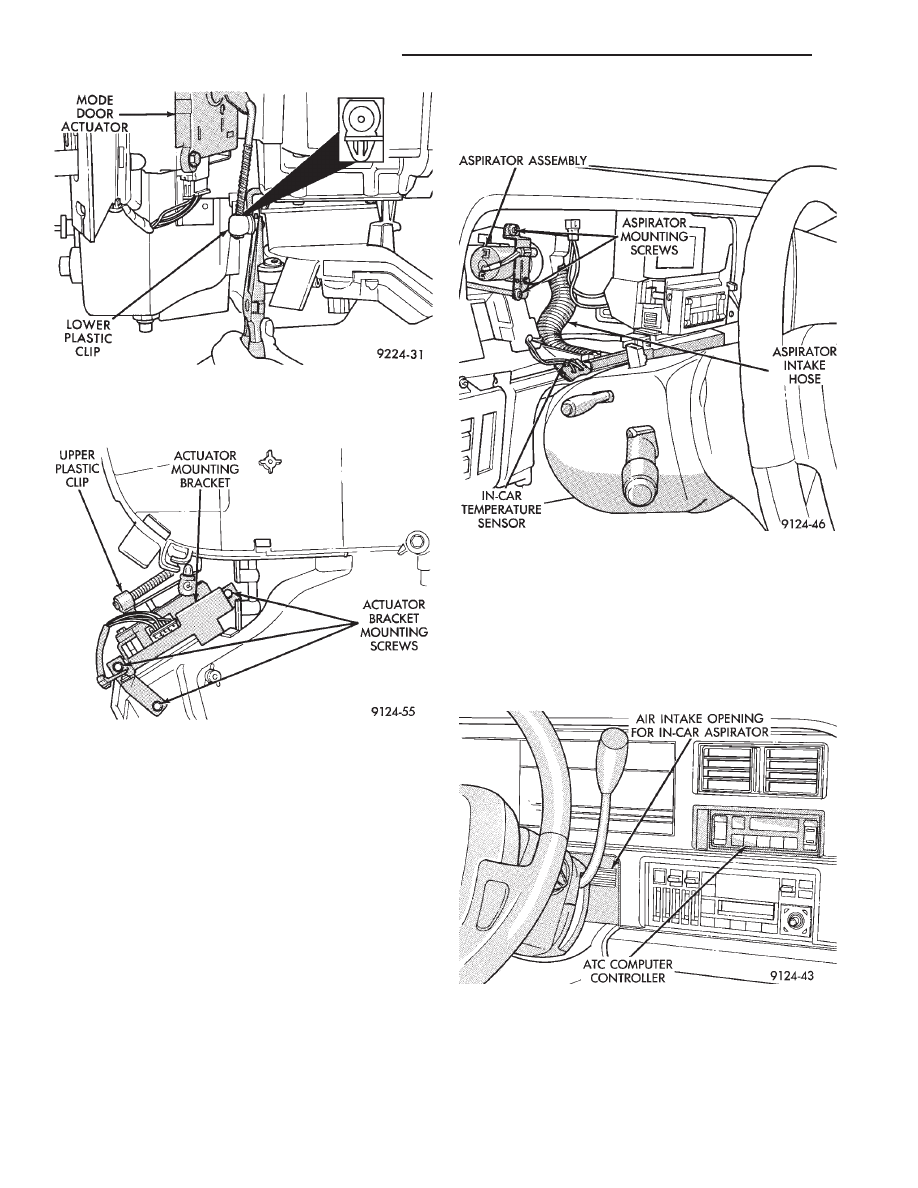
(4) Remove the three actuator bracket mounting
screws (Fig. 13).
(5) Rotate actuator to gain access to upper plastic
clip. Pinch and remove the upper plastic clip from
the actuator arm.
(6) Remove actuator-to-actuator mounting bracket
screws.
(7) Remove actuator from mounting bracket. Re-
move from vehicle.
To install, reverse the preceding operation.
IN-CAR TEMPERATURE SENSOR/ASPIRATOR
ASSEMBLY
The ATC system uses various sensors which return
electrical signals to the computer control. The in-car
temperature sensor is part of a motorized aspirator
assembly (Fig. 14) that is mounted in the instrument
panel. A small fan (in the aspirator) draws air
through an intake on the instrument panel. This air
flows over a thermistor which picks up temperature
variations. The computer control then makes system
adjustments to maintain a constant passenger com-
partment temperature. The in-car temperature sen-
sor/aspirator assembly is not serviceable and must be
replaced if found to be defective.
The In-Car Temperature Sensor/Aspirator Assem-
bly is located behind the instrument panel and to the
right of the steering column. The air intake opening
for the aspirator is located to the right of the steer-
ing column (Fig. 15). The Sensor and Aspirator are
wired together and must be replaced as an assembly.
REMOVAL AND INSTALLATION
(1) Remove the instrument cluster assembly. Refer
to Cluster and Gauge Service section in Group 8E.
(2) Un-snap the sensor from the instrument panel
(Fig. 16).
Fig. 12 Plastic Clip on Mode Door Actuator
Fig. 13 Actuator Bracket Mounting Screws
Fig. 14 In-car Temperature Sensor/Aspirator
Assembly
Fig. 15 Aspirator Air Intake
24 - 70
HEATING AND AIR CONDITIONING
Ä

(3) Remove the two aspirator mounting screws.
(4) Disconnect the aspirator intake hose from the
instrument panel.
(5) Remove sensor/aspirator and it’s wiring har-
ness from vehicle.
To install, reverse the preceding operation.
WATER TEMPERATURE SENSOR
The water temperature sensor is located on the
heater core mounting plate (Fig. 17). This is a ther-
mistor which will pick up on the engines coolant
temperature. The computer control uses this informa-
tion to control the cold engine lockout time. The wa-
ter temperature sensor is not serviceable and must
be replaced if found to be defective.
The Water Temperature Sensor is located on the
heater hose mounting plate between the heater hose
nipples.
REMOVAL AND INSTALLATION
(1) The A/C-heater housing assembly must be re-
moved for Water Temperature Sensor replacement.
Refer to Heater-A/C Unit Housing Removal and In-
stallation—AC/AY Body for procedures.
(2) Remove sensor mounting screw (Fig. 18).
(3) Disconnect the sensor pigtail wiring harness
from the main wiring harness and remove sensor
from vehicle.
To install, reverse the preceding operation. When
tightening the sensor mounting screw, allow the sen-
sor to rotate and contact the upper heater hose nip-
ple. This will aid in sensor efficiency.
SUN SENSOR
The sun sensor (Fig. 19) is mounted on the driver
side of the vehicle on top of the instrument panel.
This is not a thermistor type sensor but rather a
photo diode. For this reason the sun sensor responds
to sun light intensity rather than temperature. It is
used to aid in determining proper mode door position.
The sun sensor is not serviceable and must be re-
placed if found to be defective.
REMOVAL AND INSTALLATION
(1) Carefully pry up the sensor from the instru-
ment panel with a screwdriver (Fig. 20). Place a rag
under the screwdriver to prevent scratching of the
instrument panel.
(2) Disconnect the sensor at the wiring harness.
To install, reverse the preceding operation. Snap
the sensor securely to the instrument panel.
Fig. 16 In-Car Temperature Sensor/Aspirator
Assembly Removal and Installation
Fig. 17 Water Temperature Sensor
Fig. 18 Water Temperature Sensor Removal and
Installation
Ä
HEATING AND AIR CONDITIONING
24 - 71

NON—COMPUTER AIDED DIAGNOSTIC TESTS
Determine whether the operator complaint is due
to a system failure or improper operation of the ATC
system. The system will to go into a maximum heat
or cooling mode if the operator changes the tempera-
ture setting four or more degrees.
Check the following:
• Coolant level
• Refrigerant charge
• Drive belt tension
• Radiator air flow
• Radiator fan operation
• Air suction of In-car Temperature Sensor/Aspirator
To check air suction of the Aspirator, place a small
piece of tissue paper over the Aspirator opening on
the instrument panel. This opening is located to the
right of the steering column. The tissue paper should
cling to the opening if system is functioning properly.
Bring the engine to normal operating temperature
and proceed with Computer Aided Diagnostic Proce-
dures. Always test the entire system after each re-
pair has been performed.
COMPUTER AIDED DIAGNOSTIC TESTS
The ATC control has a computer capable of trou-
bleshooting the entire ATC system in approximately
60 seconds. The engine must be running and at nor-
mal operating temperature during the test to provide
hot coolant for the heater.
During the ATC Diagnostic Test, the computer will
calibrate the Mode and Blend Door actuators.
CAUTION: Do not remove the actuators from the
heater-A/C unit assembly with power applied. Re-
moval should only be done with the Ignition OFF.
The actuators have no mechanical stops to limit the
travel. If the actuator rotates and is not connected
to the unit assembly, it will become un-calibrated.
The Diagnostic Test is capable of checking all elec-
trical signals between the ATC Control Module, ac-
tuators, sensors and blower control.
The Diagnostic Test will display two types of Diag-
nostic trouble Codes (Fig. 21). The Diagnostic Trou-
ble Codes numbered 01 through 22, have been
detected during the Diagnostic Test. Diagnostic Trou-
ble Codes numbered 23 through 28, have been de-
tected during normal ATC operation. Diagnostic
Trouble Codes 23 through 28 would then be stored in
the ATC control computer and are only being re-
trieved during the Diagnostic Test.
For electrical pin numbers, refer to the wiring Pin
out charts on the following pages in this section.
(1) Start vehicle and allow engine to warm up.
(2) For
two
seconds,
depress
the
DEFROST,
FLOOR and MODE buttons at the same time. The
ATC control should begin to flash on and off.
(3) During the Diagnostic Test perform the follow-
ing symptom tests:
(a) Do all display symbols and indicators illumi-
nate ?
Fig. 19 Sun Sensor
Fig. 20 Sun Sensor Removal
Fig. 21 Automatic Temperature Control Diagnostic
Trouble Codes
24 - 72
HEATING AND AIR CONDITIONING
Ä
(b) Does the blower motor operate at its highest
speed ?
(c) Feel the outlet temperature. Does it get hot
and then cycle cold ?
(d) Does the air flow switch from DEFROST out-
lets and then cycle to PANEL outlets?
If you can answer NO to any of these questions,
proceed to step 4, otherwise proceed to step 5.
(4) If you answered NO to:
SYMPTOM A
The display symbols and indicators do not illumi-
nate. Diagnostic Trouble Codes are not displayed.
TEST
After self-diagnostic test is complete, select a mode
that will display the malfunction.
ACTION
If the ATC system operates properly, and the dis-
play does not, replace ATC control panel computer.
SYMPTOM B
The blower motor does not operate.
CAUTION: Stay clear of blower motor and power
module (PM) heat sink. Do not run system for more
than 10 minutes with PM removed from A/C unit.
TEST
Check all power module and blower motor connec-
tions. Use a voltmeter to test for 12 volts (ignition)
at both ends of the fuse with ignition ON. If fuse is
good, test the green wire at the blower motor connec-
tor for 12 volts (ignition) to body ground.
Turn ignition to the ON position.
With the blower motor still connected, check for 12
volts to body ground on the black/tan wire of the
blower motor two way connector.
Check for 12 volts at the Power Module pin #4
(BK/TN).
Check for continuity from the Power Module pin
#3 (BK) to chassis ground.
Replace the Power Module.
ACTION
If 12 volts is not detected, repair feed circuit. Refer
to the Front Wheel Drive Car-Wiring Diagrams Ser-
vice Manual.
If 12 volts is not detected, repair wires of the
blower motor or replace the blower motor.
If 12 volts is not present, repair wire from the
blower motor connector to the Power Module.
If circuit is open, repair ground circuit of the Power
Module.
Replace the Power Module (power transistor open).
SYMPTOM C
The outlet air temperature does not become hot
and then cycle to cold during self-test operation. Di-
agnostic Trouble Codes are not displayed.
TEST/ACTION
Make sure the blend-air door is properly attached
to the actuator.
If cold air is not discharged from the outlets, check
the base A/C refrigerant system.
Make sure heating operation works correctly, (wa-
ter level, thermostat, heater hoses, heater core, etc.).
SYMPTOM D
Air does not flow from DEFROST outlets and then
cycle to PANEL outlets during self-test operation.
TEST/ACTION
Check linkages from the mode door actuator for
binding.
Check for proper door travel in the unit.
(5) The computer will do one of two things:
• Will return to the control settings that were se-
lected before the Diagnostic Test was started. This
means the test is over. If Diagnostic Trouble Codes
did not occur, and answers to questions (a), (b), (c),
and (d) were YES, the entire system is operating cor-
rectly.
• The blower motor will stop and the computer will
flash a Diagnostic Trouble Code number from 01
through 28. Record the number and then depress the
PANEL button to advance to the next test. If the
ATC control flashes one or more codes 23 to 28, the
digits on the display will flash alternating Zeros. If
you do nothing, these codes will remain stored within
the ATC control computer. After all repairs have
been made erase fault codes. Refer to Erasing Diag-
nostic Trouble Codes 23 through 28 from ATC Con-
trol in this section.
Repair all Diagnostic Trouble Codes in the order
that they have been indicated, and then retest the
system. If any blend door test fails, all remaining
blend door tests will be skipped. IF any mode door
tests fail, all remaining mode door tests will be
skipped.
Diagnostic Test can be stopped at any time by de-
pressing any button other than PANEL.
DIAGNOSTIC TROUBLE CODE DEFINITIONS
Non-computer aided diagnostics should be per-
formed first. Hood of vehicle should be closed during
the diagnostic test to keep engine heat from effecting
the ambient temperature sensor.
Also refer to the wiring Pin out charts.
• DIAGNOSTIC TROUBLE CODE 1
Involves the wiring or the ATC control head.
• DIAGNOSTIC TROUBLE CODES 2, 13, 14, 15,
20, and 23
Ä
HEATING AND AIR CONDITIONING
24 - 73
Нет комментариевНе стесняйтесь поделиться с нами вашим ценным мнением.
Текст