Chrysler Le Baron, Dodge Dynasty, Plymouth Acclaim. Manual — part 203
Involves the wiring, blend-air door actuator, or the
ATC control head.
• DIAGNOSTIC TROUBLE CODES 3, 16, 17, 18, 19,
and 24
Involves the wiring, mode door actuator, or the ATC
control head.
• DIAGNOSTIC TROUBLE CODE 4
Involves the wiring, blend-air door actuator, mode
door actuator, fresh/recirc. door actuator, or the ATC
control head.
• DIAGNOSTIC TROUBLE CODE 5
Involves the wiring, fresh/recirc. door actuator, or the
ATC control head.
• DIAGNOSTIC TROUBLE CODE 6
Involves the compressor circuit signal wiring, or the
ATC control head.
• DIAGNOSTIC TROUBLE CODE 7
Involves the blower wiring, power module, or the
ATC control head.
• DIAGNOSTIC TROUBLE CODES 8, 21, 22
Requires replacing the ATC control head.
• DIAGNOSTIC TROUBLE CODES 9, and 27
Involves the wiring, sun sensor, or the ATC control
head.
• DIAGNOSTIC TROUBLE CODES 10, and 28
Involves the wiring, water temperature sensor, or the
ATC control head.
• DIAGNOSTIC TROUBLE CODES 11, and 25
Involves the wiring, ambient temperature sensor, or
the ATC control head.
• DIAGNOSTIC TROUBLE CODES 12, and 26
Involves
the
wiring,
in-car
temperature
sensor/aspirator, or the ATC control head.
DIAGNOSTIC TROUBLE CODE SERVICE PROCE-
DURES
The control keyboard will not function if pins
7, 9, 17, 19, or 20 of the 21-way wiring connector
are shorted to battery voltage.
For electrical pin numbers, refer to the wiring Pin
out charts (Figs. 1, 2, 3, 4, 5, or 6).
DIAGNOSTIC TROUBLE CODE 1—OUTPUT
FAILURE WITH ALL OUTPUTS LOW
(1) Remove pin #2 from 21-way connector on control
and retest system. If code 01 does not appear, the
control is good.
Disconnect 21-way connector from control. With an
ohmmeter, measure the resistance between pin #2 and
pin #12 of 21-way. This should be between 2,600 and
2,800 ohms. If yes, the power module is good.
Source of voltage on pin #2 is in the wiring. Repair
and retest system.
(2) Remove pin #13 from 21-way connector on con-
trol and retest system. If code 01 does not appear, the
control is good. Locate source of voltage on pin #13.
Repair and retest system.
(3) Remove pin #5 from 21-way connector on control
and retest system. If code 01 does not appear, the
control is good. Locate source of voltage on pin #5.
Repair and retest system.
(4) Remove pin #6 from 21-way connector on control
and retest system. If code 01 does not appear, the
control is good. Locate source of voltage on pin #6.
Repair and retest system.
(5) Remove pin #15 from 21-way connector on con-
trol and retest system. If code 01 does not appear, the
control is good. Locate source of voltage on pin #15.
Repair and retest system.
DIAGNOSTIC TROUBLE CODE 2—BLEND AC-
TUATOR DRIVE SIGNAL NOT HIGH
If both Diagnostic Trouble Codes 2 and 3 occur
simultaneously, do both procedures. There is
typically only 1 failure.
(1) Disconnect terminal #6 on the ATC control 21-
way connector and retest the system. Note that remov-
ing this terminal may generate additional Diagnostic
Trouble Codes. Disregard these at this time.
(2) If Diagnostic Trouble Code 2 reappears, replace
control.
(3) If code 2 does not reappear, the problem is a
shorted blend door actuator motor or a short to ground
in circuit 33 (pin #6).
(4) Remove 21-way connector and check for continu-
ity from pin #6 to chassis ground. There should not be
any continuity. If continuity is there, repair wiring and
retest.
(5) Check resistance across pins #6 and #4 of the
21-way for a shorted actuator motor. Resistance should
be between 20 and 50 ohms. If not correct, replace
actuator.
DIAGNOSTIC TROUBLE CODE 3—MODE AC-
TUATOR DRIVE SIGNAL NOT HIGH
If both Diagnostic Trouble Codes 2 and 3 occur
simultaneously, do both procedures. There is
typically only 1 failure.
(1) Disconnect terminal #5 on the ATC control 21-
way connector and retest the system. Removing this
terminal may generate additional Diagnostic Trouble
Codes. Disregard these at this time.
(2) If Diagnostic Trouble Code 3 reappears, replace
control.
(3) If code 3 does not reappear, the problem is a
shorted mode door actuator motor, or a short to ground
in circuit #35 (pin #5).
(4) Remove 21-way and check for continuity from pin
#5 to chassis ground. There should not be any continu-
ity. If continuity is there, repair wiring and retest.
24 - 74
HEATING AND AIR CONDITIONING
Ä
Fig. 1 Pin outs for 21-way Connector at ATC Computer Connector
Ä
HEATING AND AIR CONDITIONING
24 - 75
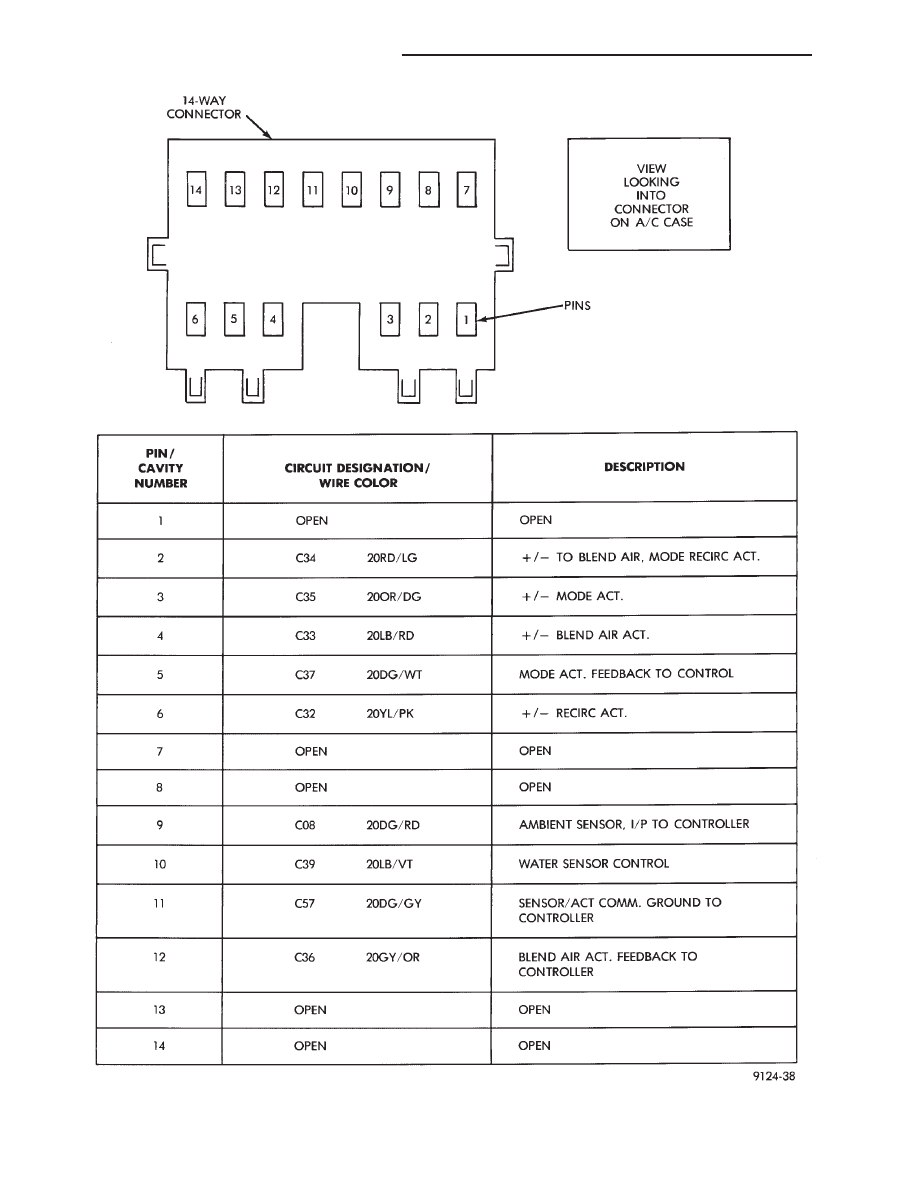
Fig. 2 Pin outs for 14-way Connector at ATC Harness on A/C Housing
24 - 76
HEATING AND AIR CONDITIONING
Ä
(5) Check resistance across pins #4 and #5 of the
21-way connector for a shorted actuator motor. Resis-
tance should be between 20 and 50 ohms. If not cor-
rect, replace actuator.
DIAGNOSTIC TROUBLE CODE 4—ACTUATOR
DRIVE COMMON SIGNAL NOT HIGH
If both Diagnostic Trouble Codes 4 and 5 oc-
cur simultaneously, do both procedures. There
is typically only 1 failure.
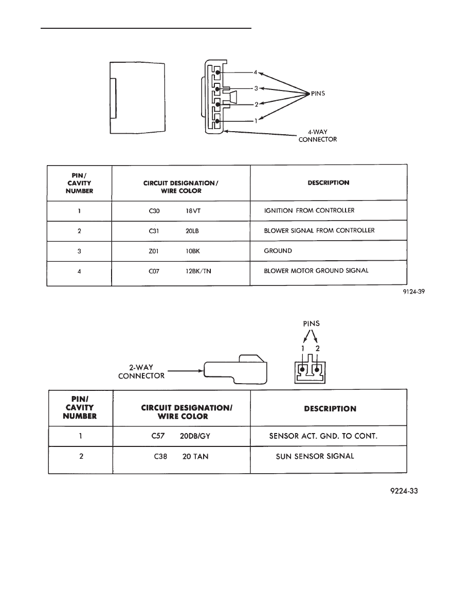
Fig. 3 Pin outs for 4-Way Connector
Fig. 4 Pin outs for Sun Sensor 2-Way Connector
Ä
HEATING AND AIR CONDITIONING
24 - 77
Нет комментариевНе стесняйтесь поделиться с нами вашим ценным мнением.
Текст