Chrysler Le Baron, Dodge Dynasty, Plymouth Acclaim. Manual — part 44
THROTTLE BODY
The throttle body assembly is located on the left
end of the intake manifold plenum (Fig. 20). The
throttle body houses the throttle position sensor and
the idle air control motor. Air flow through the throt-
tle body is controlled by a cable operated throttle
blade located in the base of the throttle body.
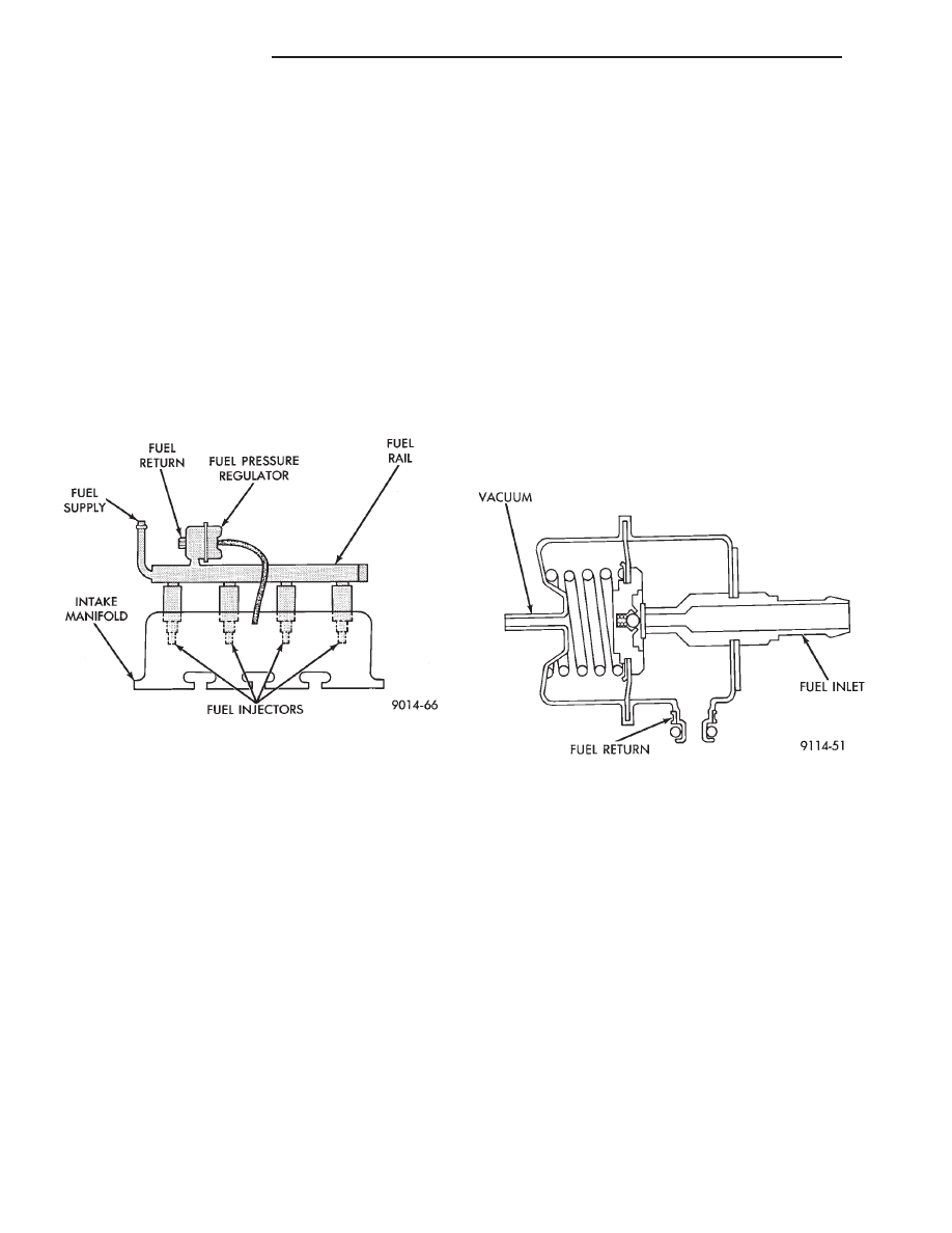
FUEL SUPPLY CIRCUIT
Fuel is pumped to the fuel rail by an electrical
pump in the fuel tank. The pump inlet is fitted with
a strainer to prevent water and other contaminants
from entering the fuel supply circuit.
Fuel pressure is controlled to a preset level above
intake manifold pressure by a pressure regulator.
The regulator is mounted on the fuel rail (Fig. 21).
The regulator uses intake manifold pressure as a ref-
erence.
FUEL INJECTORS AND FUEL RAIL ASSEMBLY
Four fuel injectors are retained in the fuel rail by
lock rings. The rail and injector assembly are in-
stalled with the injectors inserted into recessed holes
in the intake manifold.
FUEL PRESSURE REGULATOR
The pressure regulator is a mechanical device lo-
cated on the fuel rail, downstream of the fuel injec-
tors (Fig. 22). The regulator maintains a constant
380 kPa (55 psi) across the fuel injector tip.
The regulator contains a spring loaded rubber dia-
phragm that covers the fuel return port. When the
fuel pump is operating, fuel flows past the injectors
into the regulator, and is restricted from flowing any
further by the blocked return port. When fuel pres-
sure reaches 380 kPa (55 psi) it pushes on the dia-
phragm, compresses the spring, and uncovers the
fuel return port. The diaphragm and spring con-
stantly move from an open to closed position to keep
the fuel pressure constant.
Fig. 21 Fuel Supply Circuit
Fig. 22 Fuel Pressure Regulator
14 - 94
FUEL SYSTEMS
Ä
2.2L TURBO III MULTI-PORT FUEL INJECTION—GENERAL DIAGNOSIS
INDEX
page
page
Fuel System Diagram
. . . . . . . . . . . . . . . . . . . . . 95
Visual Inspection
. . . . . . . . . . . . . . . . . . . . . . . . . 95
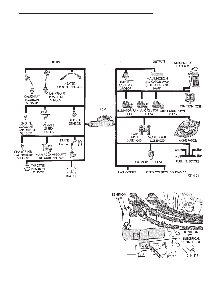
FUEL SYSTEM DIAGRAM
Refer to the System Operation portion of this sec-
tion for descriptions of the components shown in Fig.
1.
VISUAL INSPECTION
Perform a visual inspection for loose, disconnected,
or misrouted wires and hoses before diagnosing or
servicing the fuel injection system. A visual check
helps save unnecessary test and diagnostic time. A
thorough visual inspection includes the following
checks:
(1) Check the ignition coil electrical connections
(Fig. 2).
(2) Verify the harness connector is attached to the
canister purge solenoid (Fig. 3).
(3) Verify the harness connector is attached to the
wastegate solenoid (Figs. 3).
Fig. 1 Multi-port Fuel Injection Components
Fig. 2 Ignition Coil Electrical Connection
Ä
FUEL SYSTEMS
14 - 95
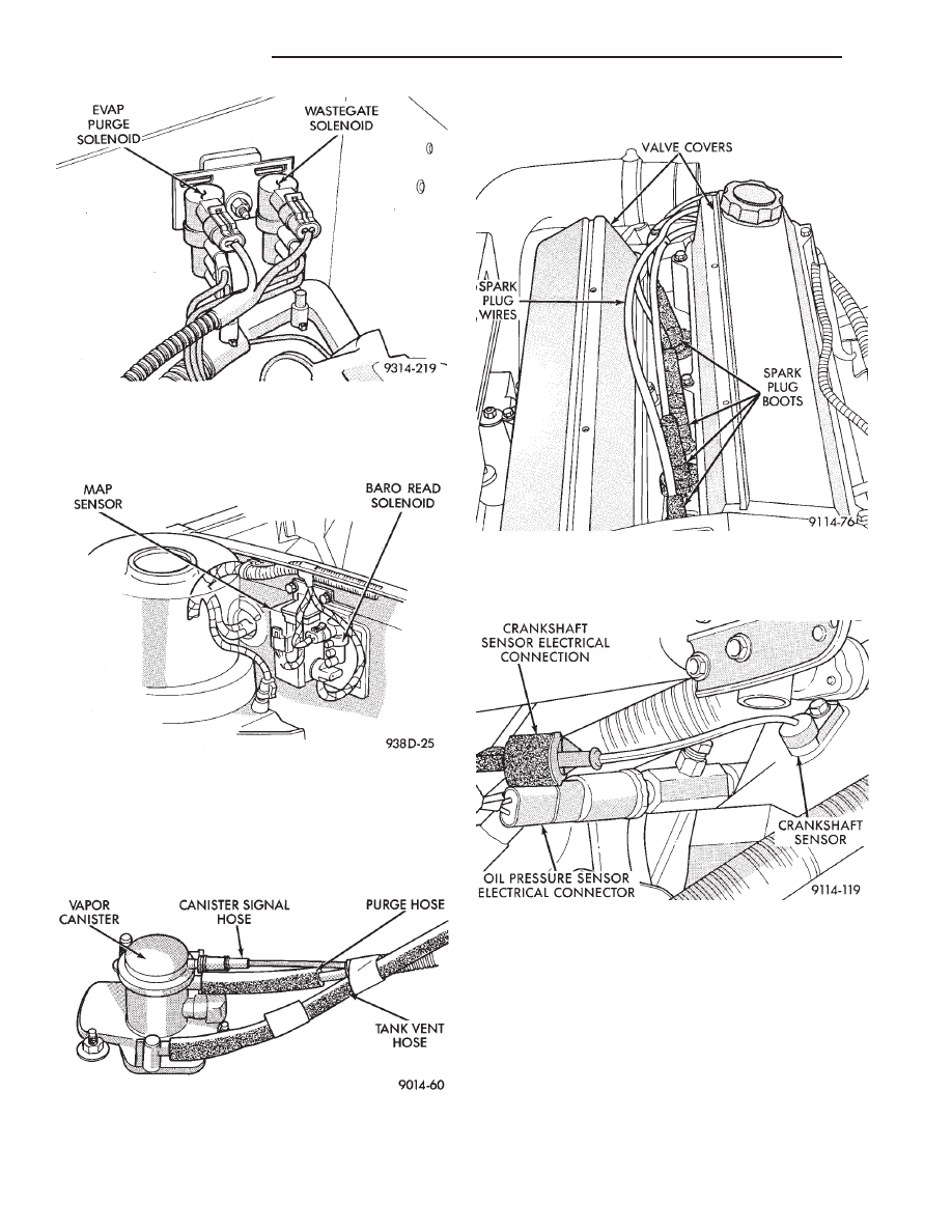
(4) Verify the harness connector is attached to the
MAP sensor (Fig. 4).
(5) Check vacuum hose connections between vac-
uum source and canister purge, wastegate, and baro-
metric read solenoids (Figs. 3 and 4).
(6) Verify hoses are securely attached to vapor
canister (Fig. 5).
(7) Verify the generator wiring and belt are cor-
rectly installed and tightened.
(8) Check ignition cable routing and attachment
(Fig. 6).
(9) Check oil pressure sending unit electrical con-
nection (Fig. 7).
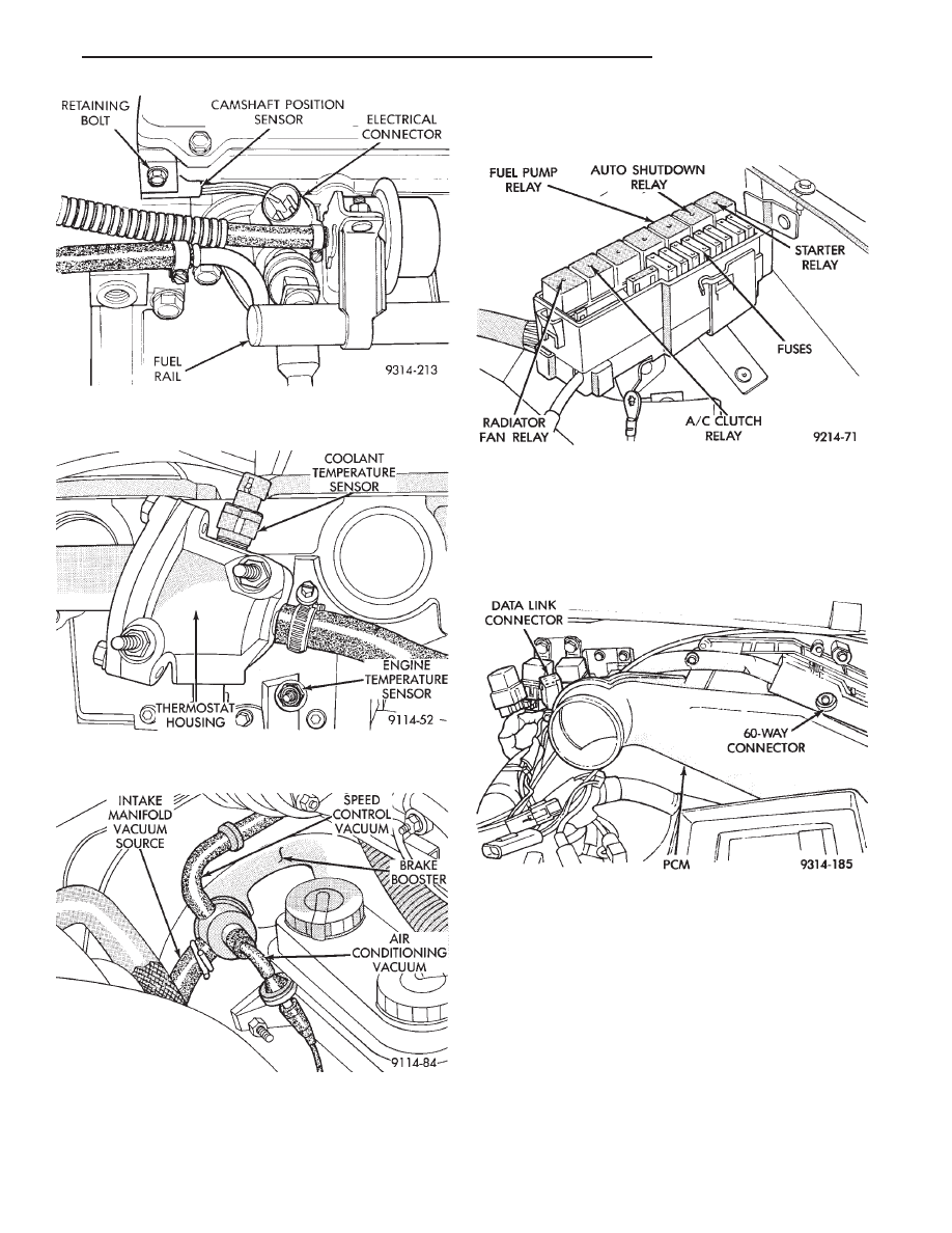
(10) Check the camshaft position sensor and crank-
shaft position sensor electrical connections (Figs. 7
and 8).
(11) Check radiator fan electrical connector.
(12) Check electrical connector at the coolant tem-
perature sensor (Fig. 9).
(13) Inspect the engine temperature sensor electri-
cal connection (Fig. 9).
(14) Check the power brake booster and speed con-
trol connections (Fig. 10).
Fig. 6 Ignition Cable Mounting and Attachment
Fig. 7 Oil Pressure Sending Unit and Crankshaft
Position Sensor
Fig. 3 Solenoid Connections
Fig. 4 Barometric/MAP Solenoid Hose Connections
Fig. 5 Vapor Canister
14 - 96
FUEL SYSTEMS
Ä
(15) Inspect the engine and fuel injector harness to
main harness electrical connections.
(16) Verify that all electrical connectors are fully
inserted into relays and that battery connections are
clean and tight (Fig. 11).
(17) Check the 60-way electrical connection at the
PCM for damage or spread terminals. Verify that the
60-way connector is fully inserted into the socket on
the PCM (Fig. 12). Ensure that wires are not
stretched or pulled out of the connector.
(18) Verify the harness connector is attached to
idle air control motor (Fig. 13).
(19) Verify the harness connector is attached to
the throttle position sensor (Fig. 13).
(20) Inspect the hose connections at throttle body
(Fig. 13).
(21) Verify all hose connections at the intake man-
ifold are secure (Fig. 14).
(22) Check vacuum hose connection between vac-
uum source and fuel pressure regulator (Fig. 15).
(23) Inspect the charge air temperature sensor
electrical connector (Fig. 15).
Fig. 8 Camshaft Position Sensor Electrical
Connection
Fig. 9 Coolant Temperature and Engine
Temperature Sensor
Fig. 10 Power Brake Booster and Speed Control
Vacuum Hose Connections
Fig. 11 Power Distribution Center
Fig. 12 PCM Electrical Connector
Ä
FUEL SYSTEMS
14 - 97
Нет комментариевНе стесняйтесь поделиться с нами вашим ценным мнением.
Текст