Chrysler Le Baron, Dodge Dynasty, Plymouth Acclaim. Manual — part 95
(3) Check solenoid to volume canister joint.
• Front strut to solenoid valve connection.
• Rear spring to solenoid valve connection.
(4) Check air line for ruptures, cuts, splits or heat
damage.
Use a soap and water solution or a liquid de-
veloped for leak detection.
SYSTEM OPERATION
ENGINE RUN OPERATION
The
system
will
compensate
for
load
addition/removal when.
• The trunk and all doors are closed.
• The engine speed exceeds 600 R.P.M.
• Throttle angle is less than 65 degrees.
• The brake is not applied.
• You are not cornering above 10 mph.
• There is not a charging system problem with the
vehicle.
ENGINE OFF OPERATION
After passengers/load is removed from the vehicle
the system will correct the vehicle attitude after:
• The trunk and all doors are closed.
• The ignition switch is in the OFF position.
Opening the a door or trunk wakes up the body
computer and the air suspension module. The air
suspension system is now capable of leveling, if
required.
LONG TERM IGNITION OFF OPERATION
The system is capable of one an additional leveling
cycle. After 2 continuous hours of ignition key off and
no door open or trunk open activities. This feature is
implemented to eliminate possible ice freeze-up be-
tween the tire and the inner fender shield.
SYSTEM OPERATION INHIBITORS
The air suspension system is inhibited when:
• The trunk is open.
• A door(s) is/are open.
• The brake pedal is engaged.
• The throttle is at the wide open position.
• The charging system fails.
The maximum compressor pump or exhaust
time is 3 minutes.
SYSTEM FAILURES
Vehicles equipped with air suspension and overhead
console. Will alert the driver of an air suspension
system malfunction. A warning Check Air Suspension
will appear on the overhead console screen.
SAFETY CONCERNS
WARNING: REAR AIR SPRINGS MUST BE DEFLATED
BEFORE BEING REMOVED FROM THE VEHICLE.
WARNING: OPEN TRUNK, OR DOOR(S) OR REMOVE
GROUND STRAP FROM BATTERY BEFORE HOIST-
ING OR JACKING A VEHICLE DURING MECHANICAL
REPAIRS.
WARNING: IF THE VEHICLE NEEDS SERVICE OR
REPAIR OF THE REAR SHOCK ABSORBERS OR
REAR AXLE PIVOT BUSHINGS. THE REAR AIR
SPRINGS MUST HAVE THE AIR PRESSURE RE-
MOVED BEFORE THE VEHICLE CAN BE SERVICED
SAFELY.
SHIPPING MODE
(1) Removing shipping height signal for customer
use.
• Use DRB II tester and 1991 Chassis (Air Suspen-
sion) service cartridge.
• Follow DRB II requirements to cancel shipping
height message in the body computer.
• Connect the Ignition Off Draw (I.O.D.) circuit.
The connection of the IOD circuit will cancel
the Shipping height signal.
(2) Return to shipping height.
• Set shipping command in the body computer using
the DRB II and the 1991 Chassis (Air suspension)
service cartridge.
• Disconnect the I.O.D. connector.
DIAGNOSIS
INITIAL DIAGNOSTIC CHECK
(1) Check for blown or missing fuses.
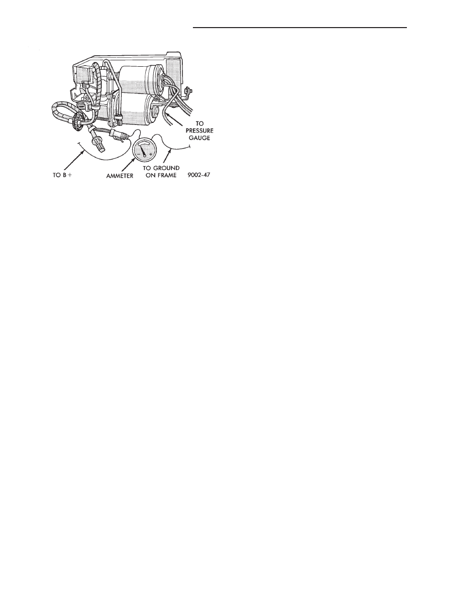
Fig. 9 Compressor Current Draw Test
2 - 78
SUSPENSION AND DRIVESHAFTS
Ä
(2) Check all connectors for correct assembly. Check
all connectors for incorrectly installed termi-
nals.
(3) Check pin #21 for minimum of 9.5 volts.
(4) Check pin #20 for minimum of 9.5 volts (with
ignition key on).
(5) Check voltage at pins #5 and #16. The measure-
ment should exceed 0 volts.
(6) Check pin #19 for continuity.
(7) The engine speed should exceed 680 rpm during
idle.
All doors and trunk must be closed for the
system to function.
DIAGNOSTICS PROCEDURES
(1) Use the D.R.B. II tester and the 1991 air suspen-
sion diagnostic service cartridge to begin the trouble-
shooting process.
(2) Use the D.R.B. mating connector under the dash
(drivers side) to plug-in the D.R.B. II test connector
(Fig. 10).
(3) The tester will conduct a complete check of the
suspension system status.
(4) The tester will list the steps to follow to access
and diagnose the failure.
(5) A Volt/Ohm meter can be used for some diagnos-
tic testing.
HEIGHT SENSOR CHECK
If a sensor signal/signals are missing. Follow the
repair procedure listed below.
(1) Check ground circuit continuity. (Remember
front and rear grounds are on different circuits.
(2) For front ground circuit continuity check circuit
S 33.
(3) For rear ground circuit continuity check circuit
X20.
(4) Refer to control module pin out chart and wiring
diagram (see Group 8F in wiring diagram manual) for
individual circuit details.
(5) If open circuits are not found replace the compo-
nent.
Complete circuit testing and connector assem-
blies before replacing a strut or right rear shock.
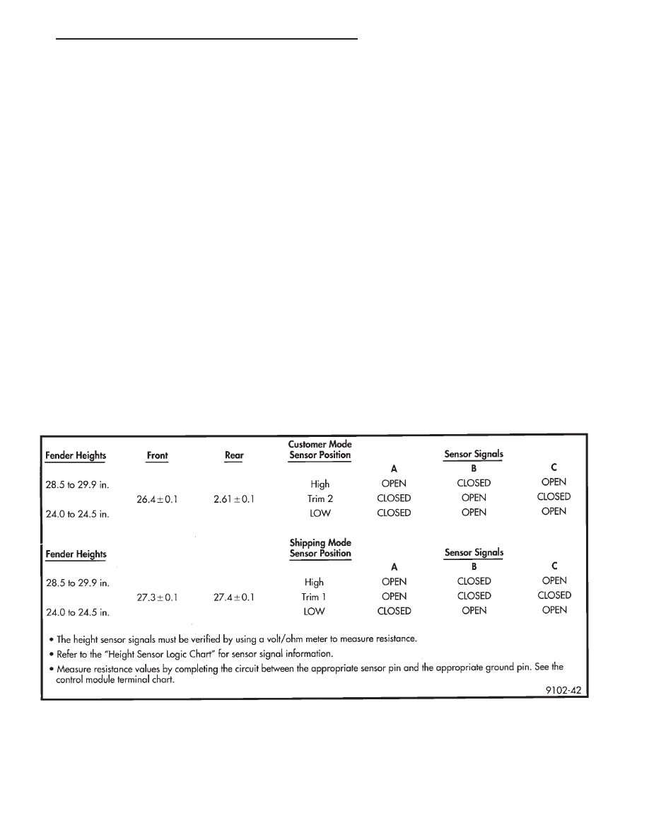
(6) To measure resistance values, see Height Sensor
Logic Chart and Initial Diagnostic Check in System
Operation.
HEIGHT SENSOR LOGIC CHART
Ä
SUSPENSION AND DRIVESHAFTS
2 - 79
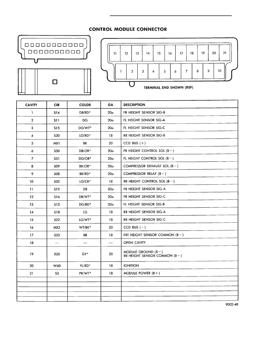
Fig. 10 Control Module Connector
2 - 80
SUSPENSION AND DRIVESHAFTS
Ä
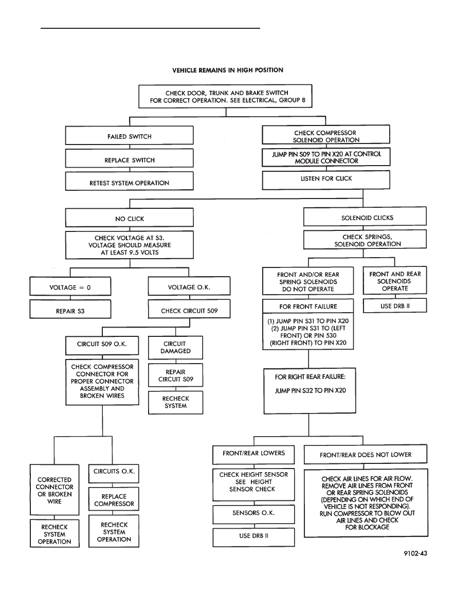
AUTOMATIC AIR SUSPENSION DIAGNOSTICS
Ä
SUSPENSION AND DRIVESHAFTS
2 - 81
Нет комментариевНе стесняйтесь поделиться с нами вашим ценным мнением.
Текст