Chrysler Le Baron, Dodge Dynasty, Plymouth Acclaim. Manual — part 96
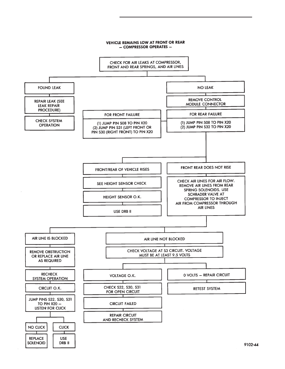
AUTOMATIC AIR SUSPENSION DIAGNOSTICS
2 - 82
SUSPENSION AND DRIVESHAFTS
Ä

AUTOMATIC AIR SUSPENSION DIAGNOSTICS
Ä
SUSPENSION AND DRIVESHAFTS
2 - 83

AUTOMATIC AIR SUSPENSION DIAGNOSTICS
2 - 84
SUSPENSION AND DRIVESHAFTS
Ä
SERVICE PROCEDURES
CONTROL MODULE (ASCM)
REMOVAL
(1) Disconnect negative battery cable.
(2) Remove right side trunk trim panel.
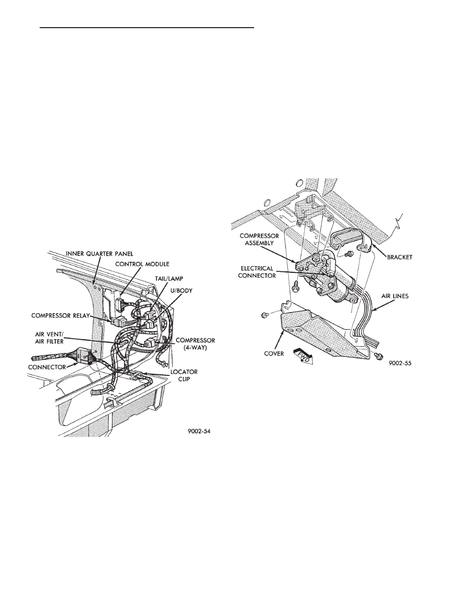
(3) Remove electrical connectors from control mod-
ule and relay (Fig. 11).
(4) Remove control module mounting screws and
remove assembly.
INSTALLATION
(1) Install relay on the control module mounting
bracket (if required).
(2) Place control module in mounting position.
(3) Install mounting screws and tighten to 2-3 N
Im
(19-29 in. lbs.) torque.
(4) Install control module and relay wiring connec-
tors (Fig. 11).
(5) Install right side trunk trim panel.
(6) Connect negative battery cable.
COMPRESSOR RELAY
REMOVAL
(1) Remove right side trunk trim panel.
(2) Remove electrical connector from relay.
(3) Remove relay from control module mounting
bracket by prying out on locating clip (Fig. 11)
INSTALLATION
(1) Push relay onto bracket (relay will Lock into
position.)
(2) Install electrical connector.
(3) Install trim panel.
COMPRESSOR ASSEMBLY
REMOVAL
(1) Disconnect battery negative cable.
(2) Raise vehicle, see Hoisting, Group 0.
(3) Remove cover from compressor assembly. Re-
move air hose (see AIR LINES) and electrical connec-
tors (Fig. 12)
(4) Remove compressor assembly mounting screws
and lower assembly from vehicle.
(5) Remove mounting bracket screws and slide
mounting bracket away from compressor.
INSTALLATION
(1) Slide mounting bracket on compressor and in-
stall screws and tighten to 8 N
Im (70 in. lbs.) torque.
DO NOT OVER TORQUE THESE SCREWS.
(2) Install compressor assembly to frame rail and
tighten screws to 8 N
Im (70 in. lbs.) torque. DO NOT
OVER TORQUE THESE SCREWS.
(3) Connect air hose and electrical connector to com-
pressor assembly.
(4) Install cover on compressor assembly and tighten
screws to 6 N
Im (40 in. lbs.) torque.
(5) Lower vehicle and connect battery negative
cable.
(6) Check operation of the system.
AIR DRYER
REMOVAL
Remove compressor assembly. See COMPRESSOR
ASSEMBLY.
Fig. 11 Control Module and Relay Wiring
Fig. 12 Compressor Assembly
Ä
SUSPENSION AND DRIVESHAFTS
2 - 85
Нет комментариевНе стесняйтесь поделиться с нами вашим ценным мнением.
Текст